ProSoft Technology 5104-DNPS-PDPM User Manual
Page 12
Functional Overview
PDPM ♦ ProLinx Gateway
Protocol Manual
PROFIBUS DP Master
Page 12 of 70
ProSoft Technology, Inc.
June 24, 2013
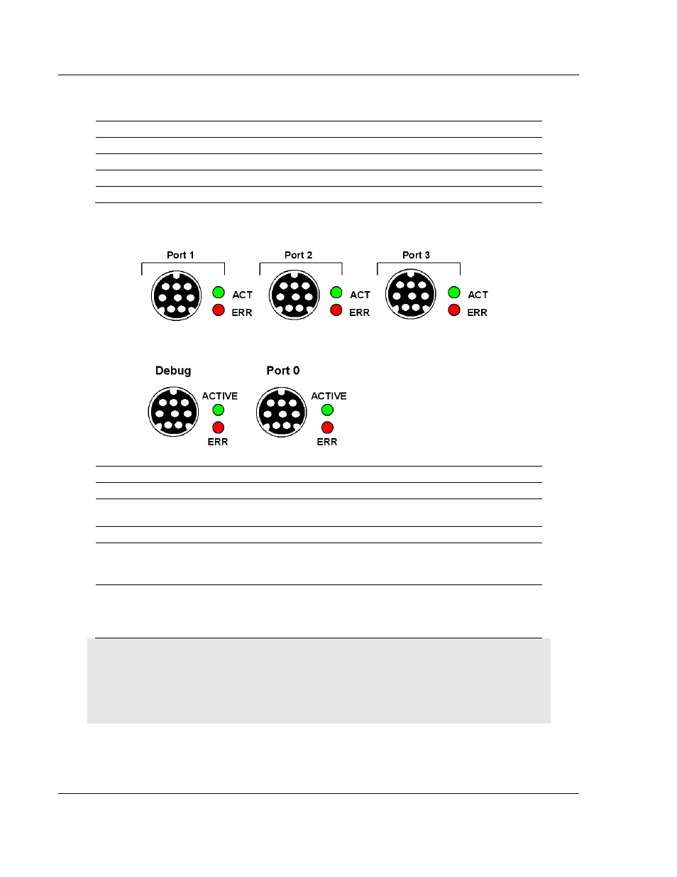
The relationship between the port labeling on the front of the ProLinx module and
the application is as follows:
Port Label
Function
Debug
Debug/Configuration
Port 0
Communication Port 0
Config
PROFIBUS Master Configuration Port
PROFIBUS Master
PROFIBUS Master Port
2.7.1 Serial Port Specifications
Type
Specifications
Serial Ports
Serial Port Adapter Cables
One Mini DIN to DB-9M adapter cable included for
each configurable serial port
Config Port Connector/ Pinout
DB-9F connector / DTE pinout
Serial Port Isolation
2500V RMS port-to-port isolation per UL 1577.
3000V DC min. port to ground and port to logic
power isolation.
Serial Port Protection
RS-485/422 port interface lines TVS diode protected
at +/- 27V standoff voltage.
RS-232 port interface lines fault protected to +/- 36V
power on, +/- 40V power off.
Note: On all ProLinx modules, data from the application port on the main board, serial Port 0, is not
buffered. Packets go directly to and from the serial chipset to the processor. This has the potential
to cause the serial communications to become erratic at baud rates above 38,400 baud.
ProLinx modules with 4 serial ports have a separate serial interface board for serial Ports 1, 2, and
3. These serial ports are buffered and can handle communications up to 115,200 baud.