Linking switcher bus and router destination, Selecting a matrix number, Defining the position of a matrix – Sony Multi Interface Shoe Adapter User Manual
Page 884
Ch
apt
884
Overall Control Panel Settings (Config Menu)
Linking Switcher Bus and Router Destination
To provide links between the switcher bus and router destination, make the
following settings as required.
Matrix selection:
Select the target of link setting from the eight matrices (1 to
8).
Matrix position definition:
Set the start address and level for the source and
destination on the S-Bus.
Link table setting:
Link a switcher cross-point button and matrix source.
Link bus setting:
Link a switcher bus address and router destination.
Selecting a matrix number
1
In the Panel >Config menu, press [Link/Program Button].
The Link/Program Button menu appears.
2
In the <Link> group, press [External Bus Link].
The External Bus Link menu appears.
The status area shows the current link status.
3
Turn the knobs to select the matrix.
In the status area, the color of the selected part changes.
4
Press [Link Matrix Set].
This confirms the matrix selection and the selected part in the status area
returns to the previous color.
To delete a link
With the link selected, press [Clear].
Defining the position of a matrix
Specify where in the 1024 × 1024 S-Bus space the link matrix is to be provided,
by setting the source and destination start address.
For the matrix selected in the External Bus Link menu, use the following
procedure.
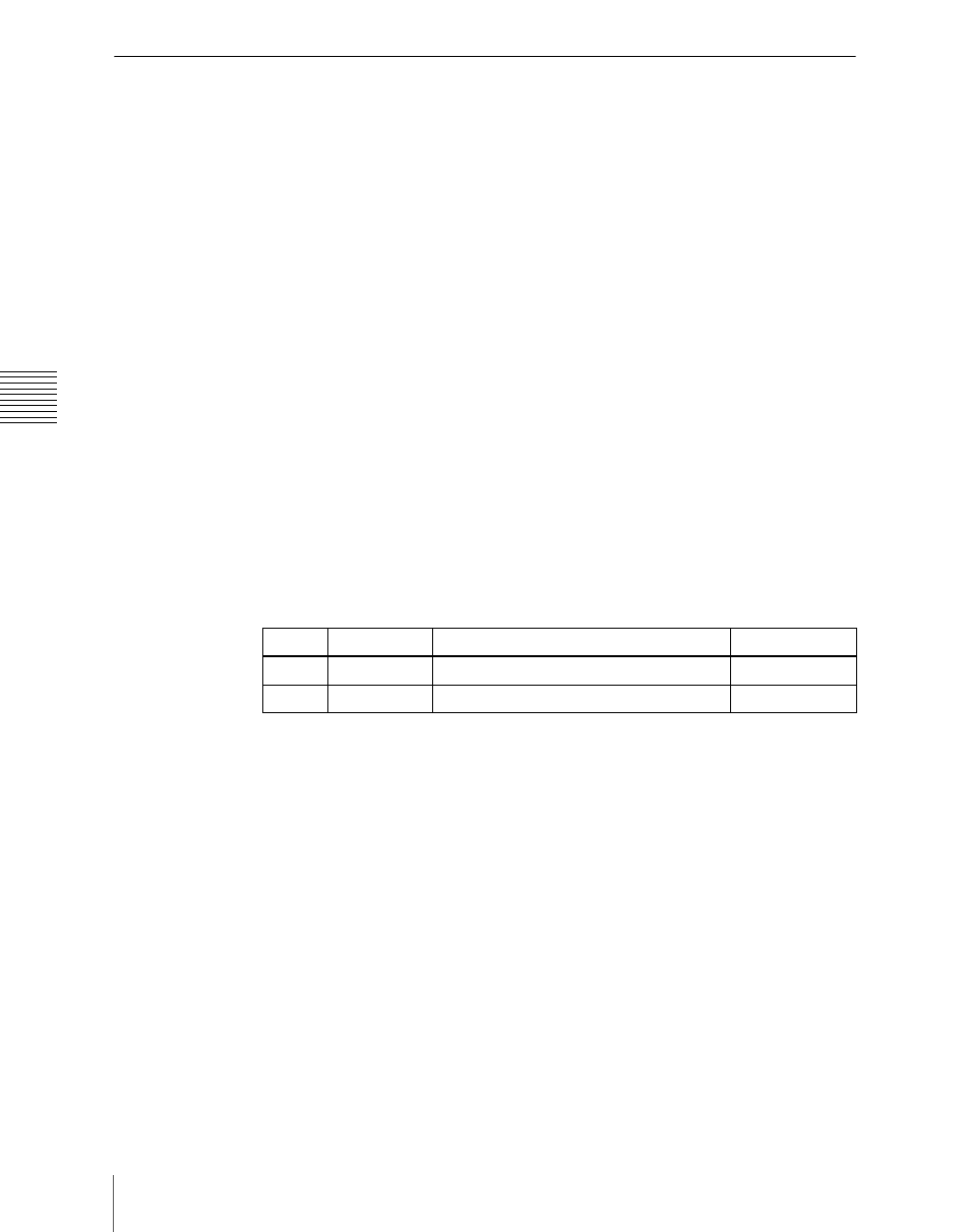
Knob
Parameter
Adjustment
Setting values
1
Link No
Link number
1 to 64
2
Link Matrix
Matrix number
1 to 8