Making a setting for linking two m/e banks, Setting the delay value – Sony Multi Interface Shoe Adapter User Manual
Page 983
983
Settings Relating to Function Links (Link Menu)
Cha
7
In the <Bus> group, select any of the following.
Enable:
Enable the GPI link setting for the selected bus.
Disable:
Disable the GPI link setting for the selected bus.
All Enable:
Enable the GPI link setting for all buses.
Setting the delay value
1
In the Switcher >Link >GPI Link Adjust menu, turn the knobs to select the
output port for which you want to set the delay value, and the
corresponding delay value.
2
Press [Delay Set].
This confirms the delay value, which is reflected in the status area.
Making a Setting for Linking Two M/E Banks
You can link any two M/E banks for some operations by using the Switcher
>Link >M/E Link menu.
The operations for which you can link two M/E banks are as follows.
• Transition execution (auto transition, cut, and fader lever operation)
• Next transition selection
• Transition type selection
Note
Clip transition execution is excluded from the above transition execution
operations.
1
In the Switcher >Link menu, press [M/E Link].
The M/E Link menu appears.
The status area displays a link list showing link source banks (M/E and
PGM/PST) and link destination banks, and a selection list.
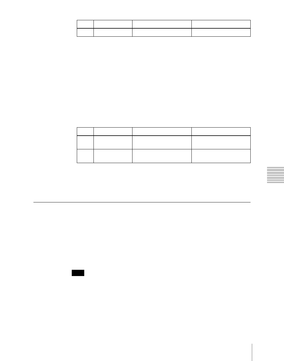
Knob
Parameter
Adjustment
Setting values
4
Bus
Bus selection
1 to 114
Knob
Parameter
Adjustment
Setting values
1
GPI Port
GPI output port for the
setting
1 to 8
5
Delay
Delay value for the output
port
0 to 300 (fields)