RCF ZM 2124 240W 6 Zones Powered Master Unit User Manual
Page 14
14
ENGLISH
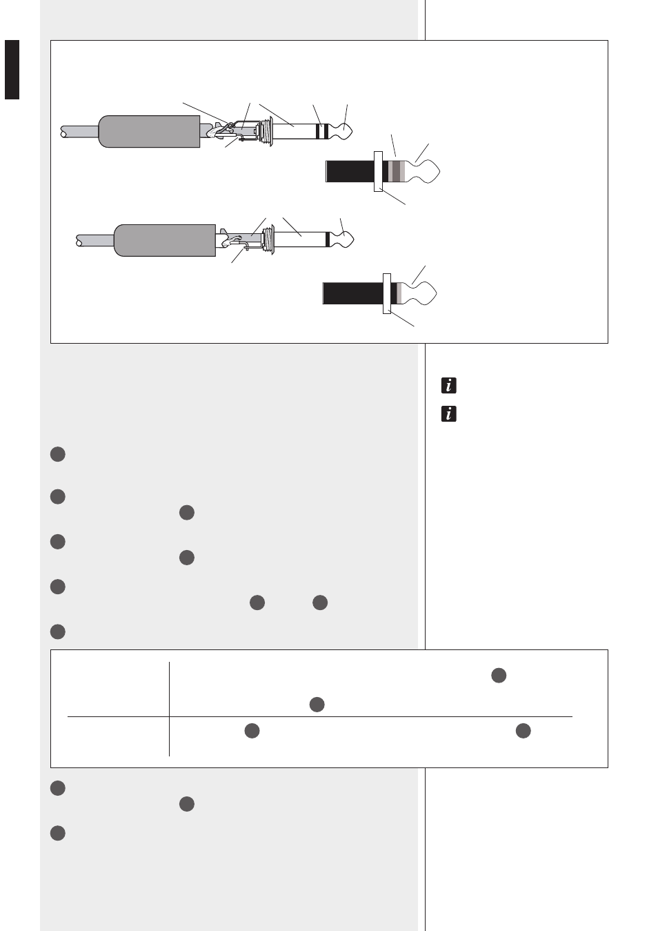
1/4” TRS JACK CONNECTOR
UNBALANCED CONNECTION
TIP:
+ HOT
SLEEVE: GND
BALANCED CONNECTION
TIP:
+ HOT
RING: – COLD
SLEEVE: GND
d
o
not
use
an
unBalanced
connection
when
the
‘p
hantom
’
power
supply
is
switched
on
!
t
he
Balanced
connection
is
always
preferaBle
,
especially
with
caBles
longer
than
5
meters
.
41
MIC/LINE 3
audio input switch.
See the MIC/LINE 4 audio input switch [39] options.
42
MIC/LINE 3
audio input (combo XLR – 1/4” jack connector)
See the MIC/LINE audio input 4
40
for the connection.
43
MIC 2
audio input (combo XLR – 1/4” jack connector)
See the MIC/LINE audio input 4
40
for the connection.
44
MIC PHANTOM
dip-switches
Phantom power ON/ OFF dip-switches for MIC 2
43
and MIC 1
46
inputs.
45
MIC 1 MODE
dip-switch
ON
All-call paging microphones (i.e. BM 3022) connected to the MIC 1 RJ 45 port
47
can make
announcements preceded by the chime with priority on the music bus.
The MIC 1 input with XLR socket
46
is muted.
OFF
The MIC 1 RJ 45
47
port has the same function of the MIC 1 input with XLR socket
46
.
The chime is disabled.
46
MIC 1
audio input (combo XLR – 1/4” jack connector)
See the MIC/LINE audio input 4
40
for the connection.
47
MIC 1
audio input (RJ 45 port)
RJ 45 port for a line made of all-call paging microphones (i.e. BM 3022).
ring
=
cold
(–)
sleeve
(
gnd
)
ring
tip
tip
=
hot
(+)
sleeve
tip
ring
sleeve
(
gnd
)
tip
tip
=
signal
sleeve
tip