Fpga programming from flash memory, Fpga programming from flash memory –15 – Altera Transceiver Signal Integrity Development Kit, Stratix V GT Edition User Manual
Page 23
Chapter 2: Board Components
2–15
Configuration, Status, and Setup Elements
May 2014
Altera Corporation
Transceiver Signal Integrity Development Kit
Stratix V GT Edition Reference Manual
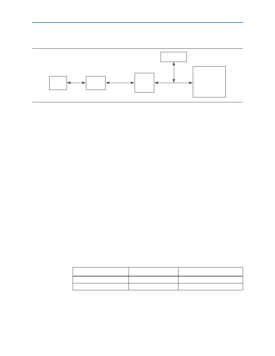
shows the block diagram for the embedded USB-Blaster connection.
MAX II CPLD System Controller
The EPM570M100 MAX II CPLD (U16) is dedicated to the on-board USB-Blaster
functionality. The CPLD connects to the FT245BL USB FIFO device on one side and
drives the JTAG signals out the other side on the general purpose I/O (GPIO) pins. A
64x16 EEPROM connects to the CPLD device and stores the factory image for
USB–JTAG functionality.
FPGA Programming from Flash Memory
On power-up, the MAX II CPLD System Controller’s parallel flash loader (PFL)
configures the FPGA from the flash memory. The system controller uses the Altera
Parallel Flash Loader (PFL) megafunction to read 16-bit data from the flash memory
and converts it to FPP format. This 8-bit data is then written to the FPGA’s dedicated
configuration pins during configuration.
The FPP configuration is implemented with an Altera MAX II CPLD together with the
Micron PC2800AP30BF 1-Gb CFI NOR-type flash device (U21). The CPLD shares the
flash interface with the FPGA. The configuration program select (PGMSEL) jumper
(J28), selects between two Programmer Object Files (.pof) files (factory or user) stored
in the flash. The configuration mode select signals, MSEL[4:0], are pulled to [00100]
FPP x16 on the board for FPP mode configuration.
There are three configuration status LEDs, CONFIG_ERR, FACTORY_IMAGE, and
USER_IMAGE
(D9, D10, D11) that indicate the status of the FPP configuration. For
information on the configuration status LEDs, refer to
lists the PGMSEL jumper settings.
Figure 2–3. Embedded USB-Blaster Connection
USB
USB Type-B
Connector
USB 2.0 PHY
USB FIFO BUS
MAX II
CPLD
JTAG
JT
A
G
JTAG Header
Stratix V GT
FPGA
Table 2–7. PGMSEL Jumper Settings
Jumper
PGMSEL Setting
File Selection
Not installed (default)
0
Factory image
Installed
1
User image