Status elements, Status leds, Status elements –18 – Altera Transceiver Signal Integrity Development Kit, Stratix V GT Edition User Manual
Page 26: Status leds –18, Fer to, Status elements” on
2–18
Chapter 2: Board Components
Configuration, Status, and Setup Elements
Transceiver Signal Integrity Development Kit
May 2014
Altera Corporation
Stratix V GT Edition Reference Manual
Status Elements
The development board includes board-specific status LEDs and switches for
enabling and configuring various features on the board, as well as a 16 character × 2
line LCD for displaying board power and temperature measurements. This section
describes these status elements.
Status LEDs
Surface mount LEDs indicate the various status of the board. A logic 0 is driven on the
I/O port to turn the LED on while a logic 1 is driven to turn the LED off.
lists the LED board references, names, and functional descriptions.
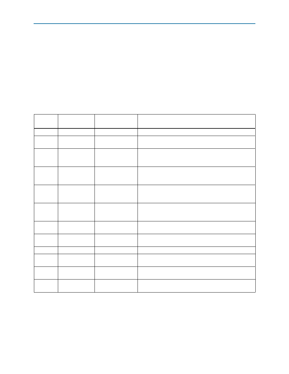
Table 2–8. Board-Specific LEDs
Board
Reference
LED Name
Schematic Signal
Name
Description
D3
POWER
—
Blue LED. Illuminates when 5-V power is active.
D7
FAN
FAN_LED
Amber LED. Illuminates when an over-temperature condition
occurs. This occurrence should automatically turn on the fan.
D8
USB
USB_LED
Green LED. Illuminates when the MAX II CPLD System Controller
is actively configuring the FPGA using the embedded
USB-Blaster.
D9
ERROR
CONFIG_ERR
Red LED. Illuminates when the MAX II CPLD System Controller
fails to configure the FPGA. Driven by the MAX II CPLD System
Controller.
D10
FACTORY
FACTORY_IMAGE
Green LED. Illuminates when the factory image is successfully
loaded into the FPGA. Driven by the MAX II CPLD System
Controller.
D11
USER
USER_IMAGE
Green LED. Illuminates when the user image is successfully
loaded into the FPGA. Driven by the MAX II CPLD System
Controller.
D12
TX
ENET_LED_TX
Green LED. Blinks to indicate Ethernet PHY transmit activity.
Driven by the Marvell 88E1111 PHY.
D13
RX
ENET_LED_RX
Green LED. Blinks to indicate Ethernet PHY receive activity.
Driven by the Marvell 88E1111 PHY.
D14
DUPLEX
ENET_LED_DUPLEX
Green LED. Illuminates to indicate Ethernet full duplex status.
D15
1000
ENET_LED_LINK1000
Green LED. Illuminates to indicate Ethernet linked at 1000 Mbps
connection speed. Driven by the Marvell 88E1111 PHY.
D16
100
ENET_LED_LINK100
Green LED. Illuminates to indicate Ethernet linked at 100 Mbps
connection speed Driven by the Marvell 88E1111 PHY.
D17
10
ENET_LED_LINK10
Green LED. Illuminates to indicate Ethernet linked at 10 Mbps
connection speed Driven by the Marvell 88E1111 PHY.