Sfp+ interface, Sfp+ interface –35 – Altera Transceiver Signal Integrity Development Kit, Stratix V GT Edition User Manual
Page 43
Chapter 2: Board Components
2–35
Components and Interfaces
May 2014
Altera Corporation
Transceiver Signal Integrity Development Kit
Stratix V GT Edition Reference Manual
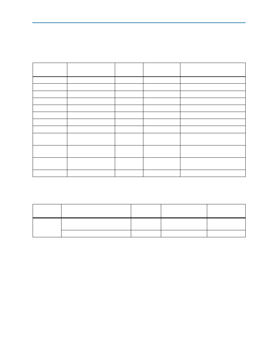
SFP+ Interface
lists the pin assignments for the SFP+ interface (SFPA) and their
corresponding schematic signal names and Stratix V GT pin numbers.
lists the SFP+ interface component reference and manufacturing
information.
Table 2–35. SFP+ Interface Pin Assignments, Signal Names and Functions
Board Reference
(J51)
Schematic Signal Name
I/O Standard
Stratix V GT
Device Pin Number
Description
19
GXB_TXLN_18
1.8-V
M35
GXB transmit
18
GXB_TXLP_18
1.8-V
M34
GXB transmit
12
GXB_RXLN_18
1.8-V
L37
GXB receive
13
GXB_RXLP_18
1.8-V
L36
GXB receive
8
SFPA_LOS
1.8-V
B28
Signal loss indicator
6
SFPA_MOD0_PRSNTN
1.8-V
B26
Module present indicator
5
SFPA_MOD1_SCL
1.8-V
A26
Two-wire serial interface clock line
4
SFPA_MOD2_SDA
1.8-V
B25
Two-wire serial interface data line
7
SFPA_RATESEL0
1.8-V
C27
Rate select 0. Controls the SFP+
interface receiver.
9
SFPA_RATESEL1
1.8-V
C26
Rate select 1. Controls the SFP+
interface receiver.
3
SFPA_TXDISABLE
1.8-V
A28
Turns off and disables the
transmitter output
2
SFPA_TXFAULT
1.8-V
A25
Transmitter fault
Table 2–36. SFP+ Interface Component Reference and Manufacturing Information
Board
Reference
Description
Manufacturer
Manufacturing
Part Number
Manufacturer
Website
J51
SFP+ connector - Mect family standard
SFP right-angle 20-pin SMT
Samtec
MECT-110-01-M-D-RA1
SFP+ cage
Molex
74754-0101