Single-phase connection diagram, Three-phase connection diagram (3 wires) – CIRCUTOR CIRe3 Series User Manual
Page 29
Advertising
CIR-e
3
Instructions manual
Pag. 29 of 50
not connect the current clamps until you reach the point in section 6.5.3 in the installation
procedure. Proceeding in this way, simplifies the interpretation of error messages displayed by
the LED indicators , showing possible connection errors installing CIR-e³.
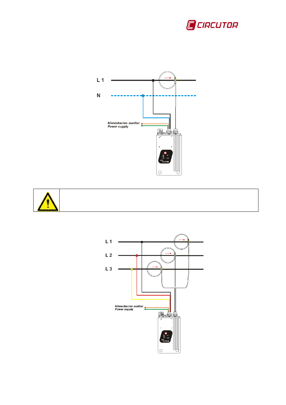
6.5.1.1 Single-phase connection diagram
Fig. 6-19 .- Single phase connection diagram
WARNING: In case of measuring in a single phase system, the voltage measuring
probes are phase L1 and Neutral (see Table 6-1 ).
6.5.1.2 Three-phase connection diagram (3 wires)
Fig. 6-20.- Three phase 3 wires connection diagram
Advertising