CIRCUTOR CIRe3 Series User Manual
Page 33
CIR-e
3
Instructions manual
Pag. 33 of 50
Once LED indicators L1/sc1, L2/sc2 and L3/sc3 are all lighting permanently, Fig. 6-23, the
user can proceed to place the current clamps clamping the bus bars or cabling.
Fig. 6-23.- Right connection indication (all LED lighting permanently)
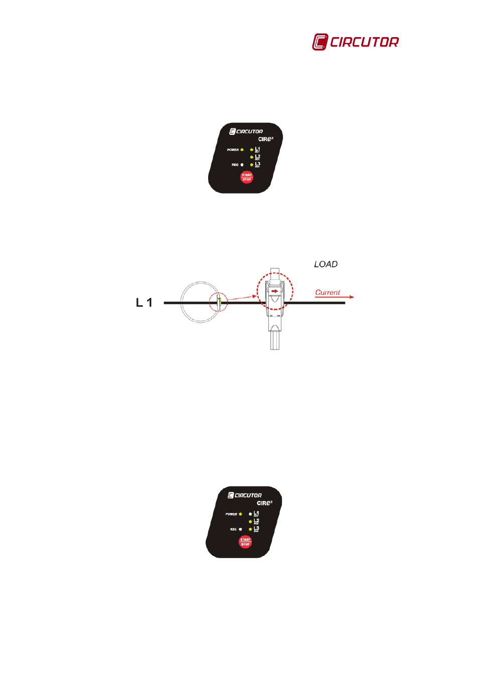
The current sensors have a standard current flow direction that must be respected for proper
recording of electrical parameters. The current flow direction is shown in the clamp itself by
drawing an arrow indicating the sense from the source (mains) to the load, as shown in Fig.
6-24.
Fig. 6-24.- Source to load current flow direction indicator
Place the current clamps and observe again the CIR-e³ LED indicators, L1/sc1, L2/sc2 and
L3/sc3, they will give the user information about possible wrong connection of current clamps.
To correctly interpret such indications, it is recommended to proceed with the connection of the
current clamps one by one, in order to detect errors individually.
When the unit detects a faulty clamp connection, that may be a negative value of active power
or a V-I phase shift greater than 60º, the Lx/csx LED , corresponding to the faulty connection
phase will start flashing. In this case, check the connection of the current clamps to make sure
that the installation follows the colour code and that the direction of the current clamps is as
shown on the previous Fig. 6-24.
Fig. 6-25.- Example of error indication (LED L1/sc1 blinking)
Example: L1/sc1 blinking, indicates a faulty clamp connection in phase L1. In this case, check
the clamp and make sure that it is tightly closed and observe that the arrow indicating current
direction is pointing from source to load. In a similar way, see that clamps L1, L2 and L3 are
installed in the proper phase, in accordance with the corresponding phase colours, which are:
BLACK for L1, RED for L2 and YELLOW for L3.