CIRCUTOR CIRe3 Series User Manual
Page 8
CIR-e
3
Pag 8 of 50
Instructions manual
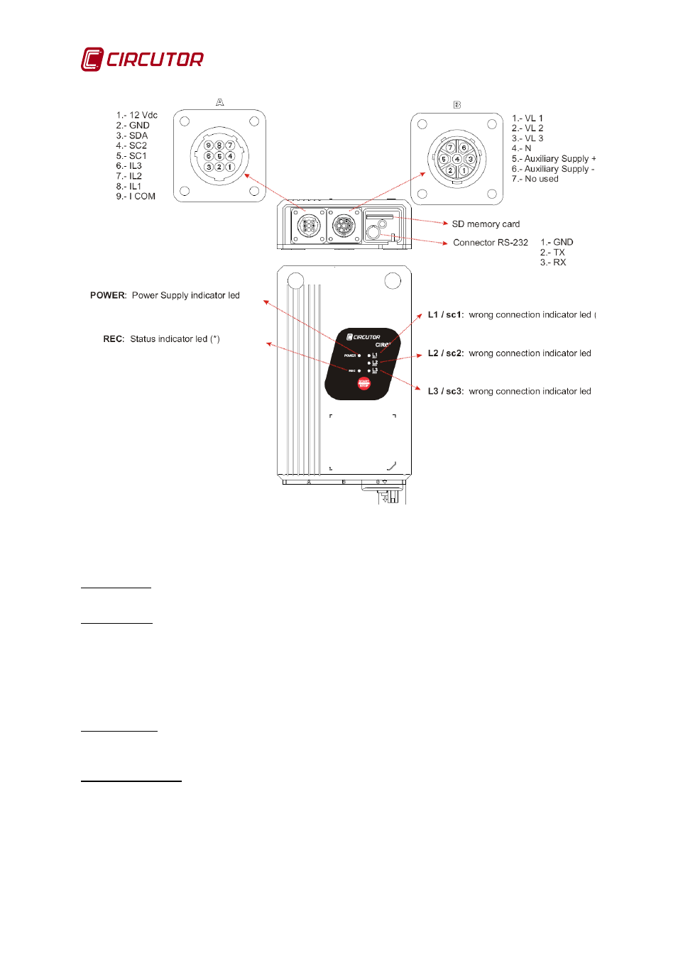
Fig. 2-1.- Front and rear view , showing connectors
Connector A is used to connect the current sensors. The Fig. 2-1 describes the functionality of
each connector.
Connector B is used to connect the voltage references of the unit. Connector B is used to
connect the voltage references of each phase (marked with VL1, VL2 and VL3), the neutral
reference (marked with N) and two additional pins (5 and 6) used to power the unit, as shown in
the figure. Terminals 5 and 6 are used to power the unit independently from the measurement,
in order to guarantee a permanent recording flow when powering the analyzer with an
uninterruptible power supply system. More information about the unit's measurement and power
supply features in section 4.1 Electrical Features.
SD card slot is used to insert the removable SD memory card to record the electrical
parameters measured by the unit. Read chapter 6.4 Insert SD card to see the position of the SD
card.
RS-232 connector is reserved for unit's firmware updating.