Three-phase connection diagram (4 wires) – CIRCUTOR CIRe3 Series User Manual
Page 30
CIR-e
3
Pag 30 of 50
Instructions manual
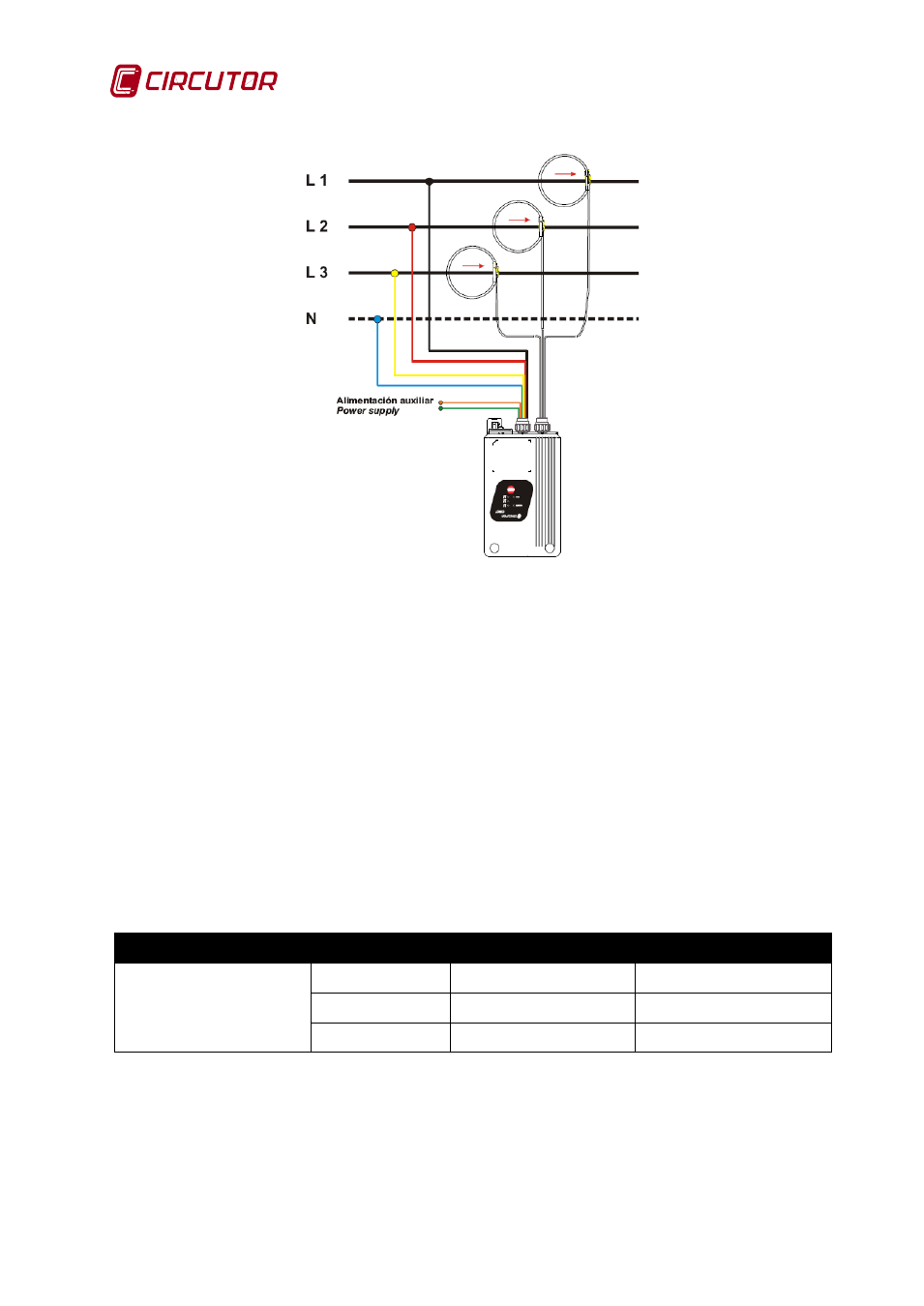
6.5.1.3 Three-phase connection diagram (4 wires)
Fig. 6-21.- Three phase 4 wires connection diagram
In case of using E-FLEX multi-scale current clamps, after powering the analyzer, the user must
configure the scale of current before starting the recording process. The scale selection process
is explained in detail the next section 6.5.2 of this manual.
6.5.2 Selecting the current scale in case of using multi-scale clamps (E-FLEX 54cm)
After connecting the voltage and current clamps and powering the unit, the POWER LED will
turn on. The CIR-e3 will then proceed to the detection of connected current clamps. In case of
using multi-scale current clamps (E-FLEX 54cm), the user should proceed to select the most
appropriate scale for measurement, based on the rated current he wants to measure.
Prior to the detailed explanation of the scale selection procedure, a table is attached with the
features of the flexible current sensor, model E-FLEX, 54 cm, which is the standard type
included with the unit.
Table 6-2 .- Standard multi-scale current transformers (clamps)
Clamp
Scale
Value
Measurement range
E-FLEX 54 cm
L1/sc1
200 A
5…200 A
L2/sc2
2.000 A
50...2.000 A
L3/sc3
20.000 A
500...20.000 A
Example 1: If the line where we have to measure, has a nominal current of 150 A, the most
suitable scale would be L1/sc1 (the lower scale), which has a full scale value of 200 A.
Example 2: If the line where we have to measure, has a nominal current of 3.000 A, the most
suitable scale would be the higher scale, L3/sc3, which has a full scale value of 20.000 A.