Current connection, Single-phase connection with monitoring – CIRCUTOR CDP-0 User Manual
Page 22
Advertising
CDP
22
Instruction Manual
Figure 17: Voltage connection diagram.
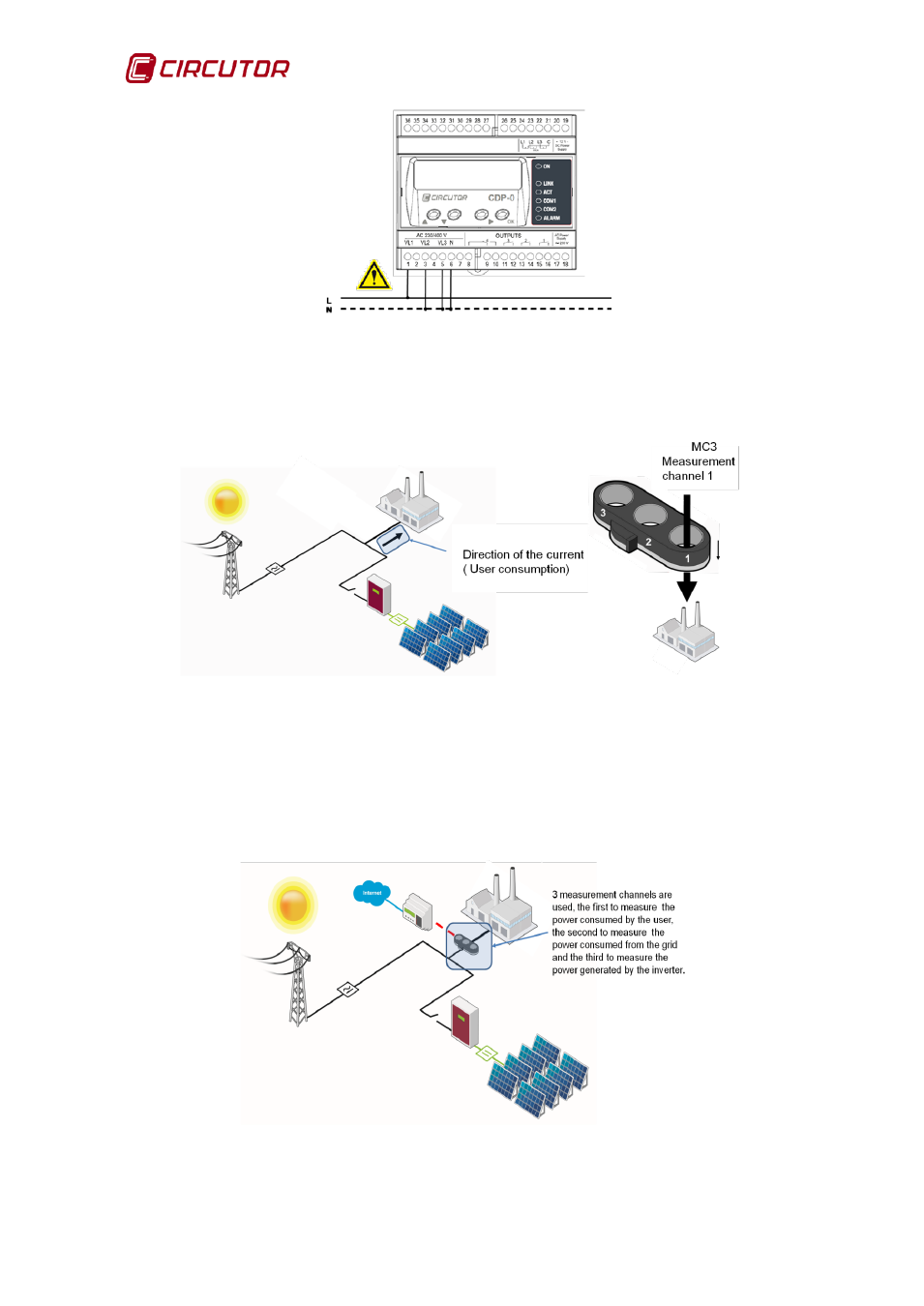
4.2.1.2. Current connection
Only one MC3 channel must be used to measure the current, in this case
number 1. The cable direction is that indicated in
Figure 18: Current connection diagram.
4.2.2. SINGLE-PHASE CONNECTION WITH MONITORING
The CDP has three voltage measuring channels (VL1, VL2 and VL3) and three
current measuring channels (IL1, IL2 and IL3) and uses an MC3 current
transformer to measure the power consumed by the user (VL1, IL1), the power
consumed from the grid (VL2, IL2) and the power generated by the inverter
(VL3, IL3).
Figure 19: Connection diagram for the single-phase measurement system with
monitoring.
Advertising
This manual is related to the following products: