Three-phase connection with monitoring – CIRCUTOR CDP-0 User Manual
Page 24
CDP
24
Instruction Manual
Figure 22: Connection diagram for the basic three-phase system.
Since this is a three-phase installation connection, each of the measuring
channels VL1, VL2 and VL3 are connected to their corresponding phase of the
three-phase grid.
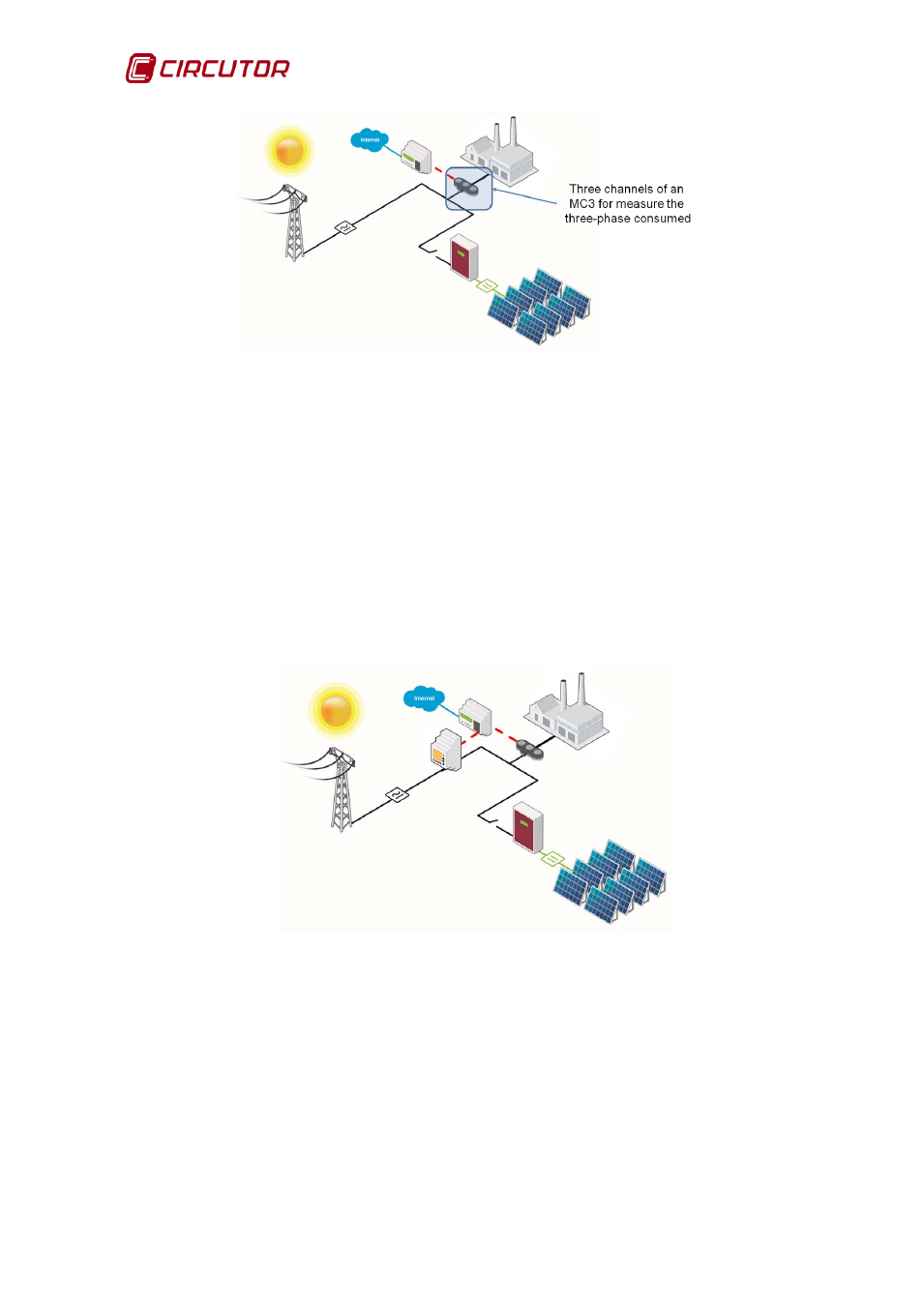
4.2.4. THREE-PHASE CONNECTION WITH MONITORING
shows a three-phase installation in which the CDP directly measures
the user's consumption, in this case a small-scale industry, by connecting an
MC3 current measurement transformer. The power control uses its RS485
channel to communicate with a CVM type three-phase measuring unit. This unit
is responsible for measuring the power consumed by the grid.
Figure 23: Connection diagram for the three-phase system with monitoring.
Since this is a three-phase installation connection, each of the measuring
channels VL1, VL2 and VL3 are connected to their corresponding phase of the
three-phase grid.