Installation, Laser, Marking – CIRCUTOR CDP-0 User Manual
Page 9
Advertising
CDP
Instruction Manual
9
3.2.- INSTALLATION
Install the unit on a DIN 46277 rail (EN 50022). All connections are located
inside the electric panel.
Terminals, opening covers or removing elements can expose parts that
are hazardous to the touch while the unit is powered. Do not use the
unit until it is fully installed.
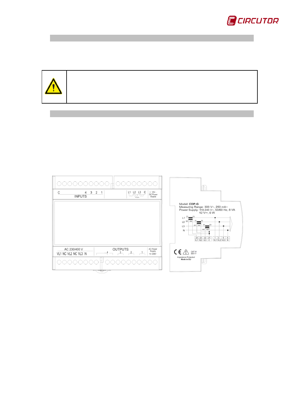
3.3.- LASER MARKING
The front view of the CDP shows that the numerical identification of the terminals
and symbols associated with their features have been marked with a laser.
The side view shows the electrical features of the unit and a diagram of its
single-phase connection, illustrating the user, grid and inverter power
measurement connection.
Figure 1: Description of the laser marking.
Advertising
This manual is related to the following products: