CIRCUTOR CDP-0 User Manual
Page 66
CDP
66
Instruction Manual
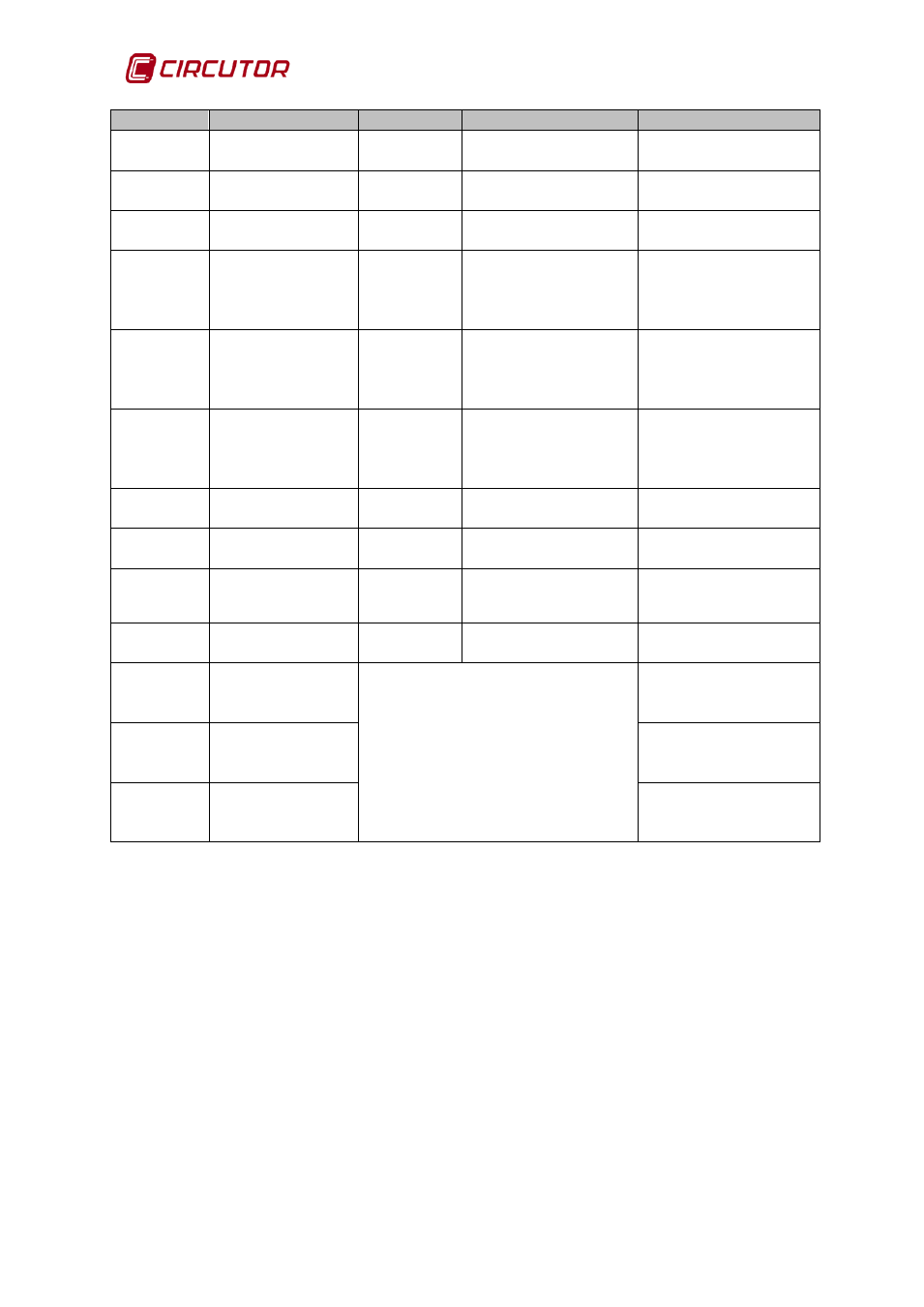
Column
Name
(2)
Units
Resolution
Description
11
GRID INJECTION
W L1
W
0.1 W
Power injected into
the phase 1 grid.
12
GRID INJECTION
W L2
W
0.1 W
Power injected into
the phase 2 grid.
13
GRID INJECTION
W L3
W
0.1 W
Power injected into
the phase 3 grid.
14
PERCENT L1
%
1%
Regulation
percentage of the
nominal power of the
phase 1 inverter
15
PERCENT L2
%
1%
Regulation
percentage of the
nominal power of the
phase 2 inverter
16
PERCENT L3
%
1%
Regulation
percentage of the
nominal power of the
phase 3 inverter
17
PV Wh
Wh
1 Wh
Energy generated by
the inverter
18
LOAD Wh
Wh
1 Wh
Energy consumed by
the load
19
GRID
CONSUMPTION
Wh
Wh
1 Wh
Energy consumed by
the grid
20
GRID INJECTION
Wh
Wh
1 Wh
Energy injected into
the grid
21
R1 STATUS
Dis : Disabled
M0: Manual mode,relay deactivated.
M1: Manual mode, relay activated.
D0:Dynamic mode,relay deactivated.
D1: Dynamic mode, relay activated.
Status of relay 1 for
managing non-critical
loads
22
R2 STATUS
Status of relay 2 for
managing non-critical
loads
23
R3 STATUS
Status of relay 3 for
managing non-critical
loads
(2)
The sign criteria in the Data Logger file:
Positive power = consumption
Negative power = generation