Data logger, Analyzers setup – CIRCUTOR CDP-0 User Manual
Page 56
CDP
56
Instruction Manual
• Relay 1, Relay 2, Relay 3: Configuration of the relays.
- Power : Power to be consumed by the load. If it is zero, the load is
considered to be deactivated.
- Min. connection time: Minimum time that a load must stay connected
before it can be deactivated, if required.
6.1.2.5. Data logger
(see
• Time between logs: time to record logs in the Data Logger: 1, 5, 10, 15
or 60 minutes.
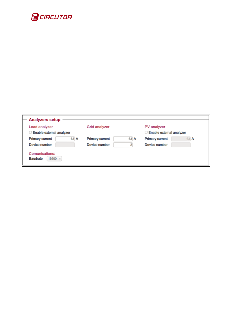
6.1.3. Analyzers setup
It is also possible to configure the communications between the CDP and the
CVM Mini or CVM Net power analyzers (
) on the web site.
Figure 73: Setup web site: Analyzers setup.
6.1.3.1. Load analyzer
• Enable external analyzer: facilitates the use of an external analyzer rather
than the CDP as a measuring unit.
• Primary current: primary value of the load analyzer of the current
transformer.
• Device number: Peripheral number of the external analyzer.
(Only activated when the “Enable external analyzer” option is activated).
6.1.3.2. Grid analyzer
• Primary current: primary value of the grid analyzer of the current
transformer.
• Device number: peripheral number of the CVM power analyzer installed to
measure the consumption of the grid.