Voltage connection, Current connection, Basic three-phase connection – CIRCUTOR CDP-0 User Manual
Page 23
CDP
Instruction Manual
23
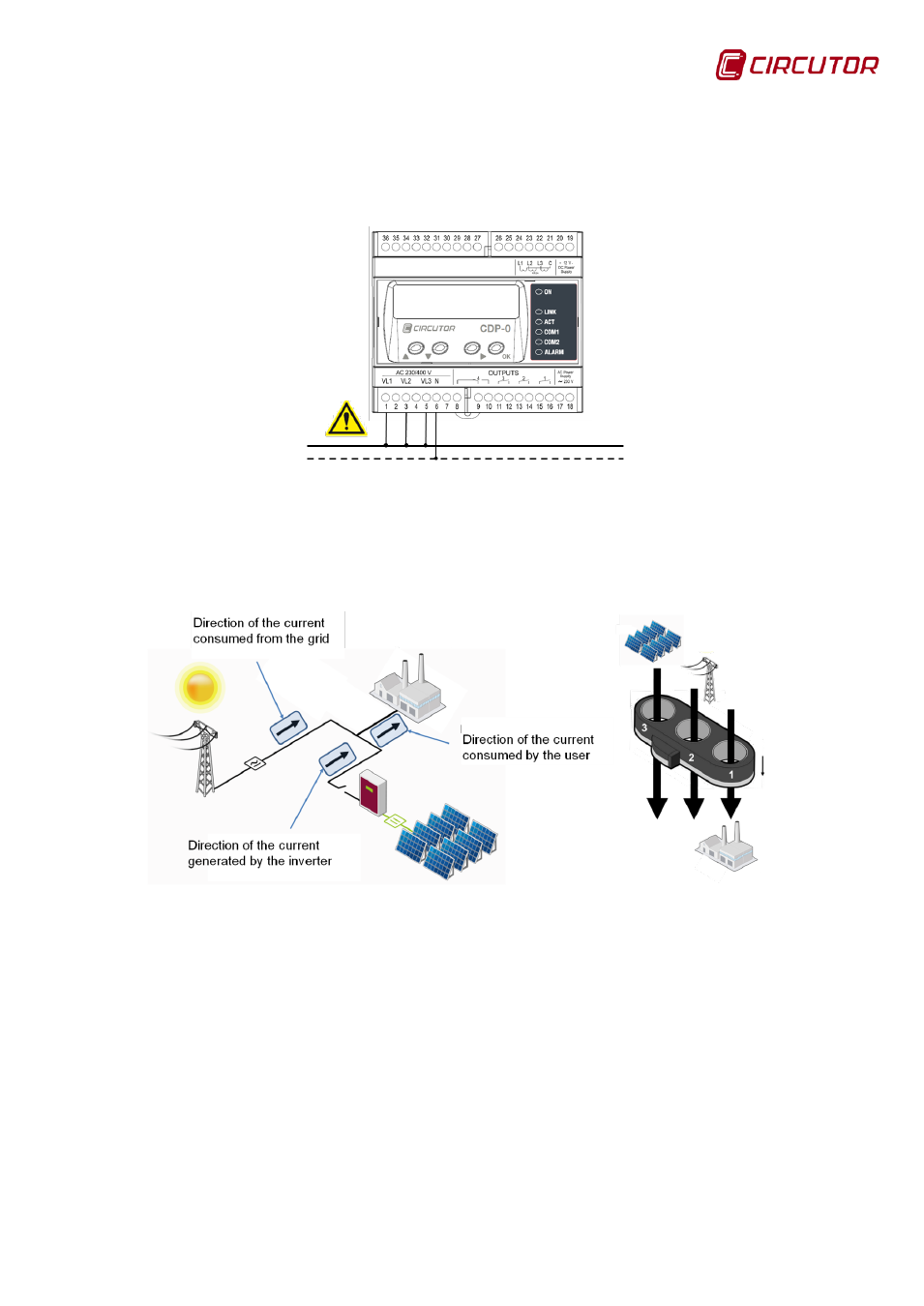
4.2.2.1. Voltage connection
For the single-phase connection with monitoring, the terminals VL1, VL2 and
VL3 must be connected and bridged and connected to the single-phase grid
phase and terminal N to the neutral.
Figure 20: Voltage connection diagram,
4.2.2.2. Current connection
The three channels of the MC3 must be used to measure the current. The cable
direction is that indicated in
Figure 21: Current connection diagram.
4.2.3. BASIC THREE-PHASE CONNECTION
The CDP has three voltage measuring channels (VL1, VL2 and VL3) and three
current measurement channels (IL1, IL2 and IL3), and will measure the three-
phase power consumed by the user using an MC3 current transformer. In this
case, since it does not measure the grid power, it cannot use the grid injection
protection relay function.