Output relay, Other options, Expandable window – Basler Electric BE1-25 User Manual
Page 16: External condition switches, Output relay -6, Other options -6, Expandable window -6, External condition switches -6
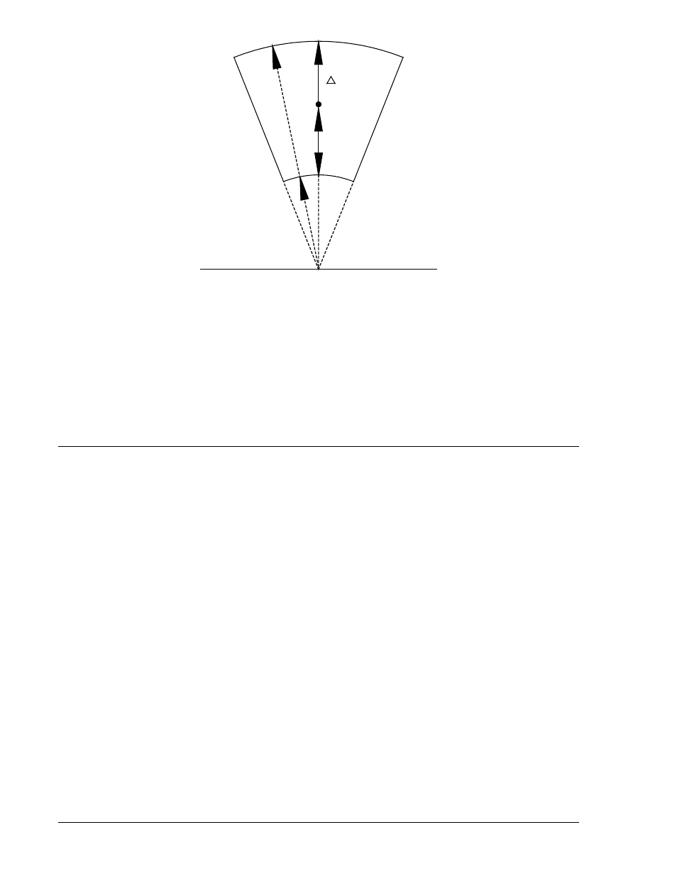
Figure 1-5. Closing Zone Diagram (Average Sensing)
Output Relay
The Voltage Monitor output relay option G or H provides additional supervision of the breaker closing
circuit, or provides an indication of the existing voltage conditions for the supervisory control system.
When a Voltage Monitor output relay is installed, the SYNC relay is no longer directly operable by voltage
monitor logic. However, the live line/live bus condition may be utilized to enable the Sync-Check function.
Detailed instructions and precautions for setting the Mode switches and Condition switches are provided
in Table 2-1, callouts R and S. The location of the switches is shown in Figure 2-2.
Voltage sensing connections are shown in Figure 4-9.
OTHER OPTIONS
Expandable Window
An expandable window (option 9 in the second position of the Style Number) is available to enable a local
operator (through a switch) or a remote dispatcher (through the supervisory control system) to expand the
preset phase angle window by a programmed ratio.
Under normal conditions, the phase angle setting is determined by the maximum angular difference that
has been calculated as suitable to meet the expected load flow of the total system. However, under
emergency conditions, the load flow throughout the system may result in excessive phase angle
separation across the opened breaker.
In order to reestablish load on a previously faulted line quickly, it may be necessary to expand the
allowable phase window. With this option, closing a contact input to the relay expands the preset phase
setting by a programmed multiple of 2 or 3 (according to the position of a jumper on the circuit card).
This option is not suggested for use in generator applications for the following reason: The phase angle
setting for a generator breaker is determined by the maximum phase difference that can be tolerated by
the generator when connected to the system. An excessive angle can result in excessive mechanical
forces in the generator and associated mountings.
Internal connections for the expandable window are shown in Figure 4-8; control circuit connections are in
Figures 4-11 and 4-12.
External Condition Switches
If a line and bus Voltage Monitor output is incorporated in the relay, the internal Condition Switches may
be functionally operated by remotely located external contacts. This capability is provided by Voltage
Monitor option 2-C, 2-U, or 2-V, but requires a voltage dropping Resistor Module to be mounted on the
relay back panel (see Figure 4-10).
V
P0004-39
VB
L
V
1-6
BE1-25 General Information
9170200990 Rev U