Basler Electric BE1-25 User Manual
Page 28
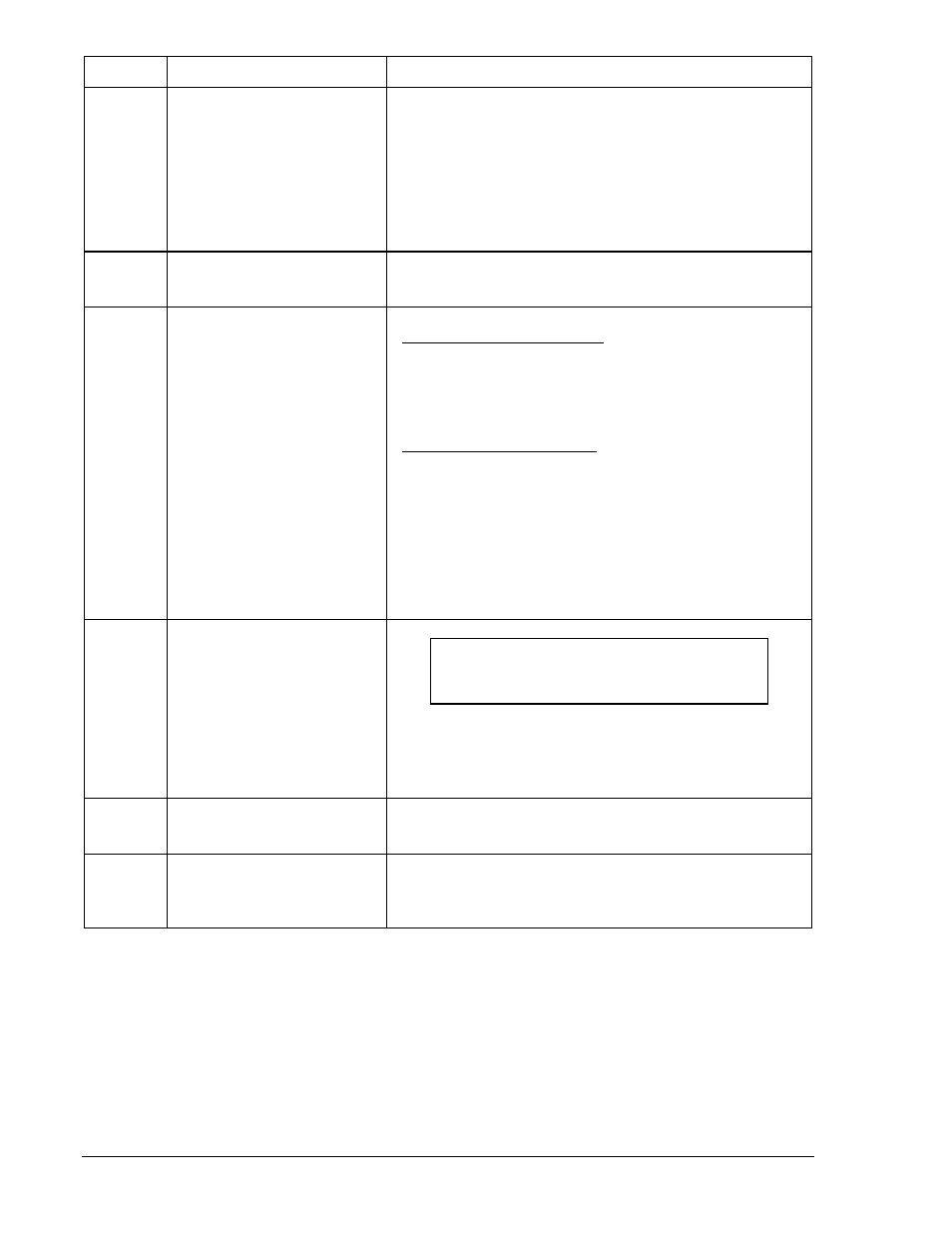
Callout
Control or Indicator
Function
L
LB Indicator
LB Adjustment
Red LED lights when bus voltage exceeds the reference
voltage established by the LB setting that defines a live
bus condition.
Continuously adjustable over a range of 10 to 135 Vac.
Adjustment is by small screwdriver through an access
hole in the front panel. CW rotation increases voltage
setting.
M
V Indicator
Red LED lights whenever the (optional) Voltage Monitor
Output relay is energized.
N
DB/NOT OV Indicator
When in the NORMAL Mode:
Red LED lights when the bus voltage is less than the
reference voltage established by the DB/NOT OV setting
that defines a dead bus condition.
When in the NOT OV Mode:
Red LED lights when the bus voltage does not exceed the
reference voltage established by the DB/NOT OV setting
that defines an overvoltage condition.
DB/NOT OV Adjustment
Continuously adjustable over the range of 10 to 135 Vac.
Adjustment is by small screwdriver through an access
hole in the front panel. CW rotation increases the voltage
setting.
O
PHASE ANGLE Selector
NOTE
A PHASE ANGLE setting of 00 inhibits
operation of the relay.
Thumbwheel switches set the acceptable maximum
phase difference between the line and bus voltages. This
phase difference window is adjustable in 1° increments
over a range of 01° to 99°.
P
PHASE ANGLE Indicator
Red LED lights when the phase angle is within the limits
established by the adjacent PHASE ANGLE Selector.
Q
Switchable jumper for
EXPAND option
Position of jumper in Figure 2-2 controls the width of the
expanded phase angle window as a multiple of the
PHASE ANGLE setting. The two positions are X2 and X3.
2-4
BE1-25 Controls and Indicators
9170200990 Rev U