Connections, Connections -9, Figure 4-8. internal diagram -9 – Basler Electric BE1-25 User Manual
Page 49: Internal circuitry, Power supply
CONNECTIONS
Be sure to check the model and style number of a relay before connecting and energizing the relay.
Incorrect wiring may result in damage to the relay. Except where noted, connections should be made with
wire no smaller than 14 AWG.
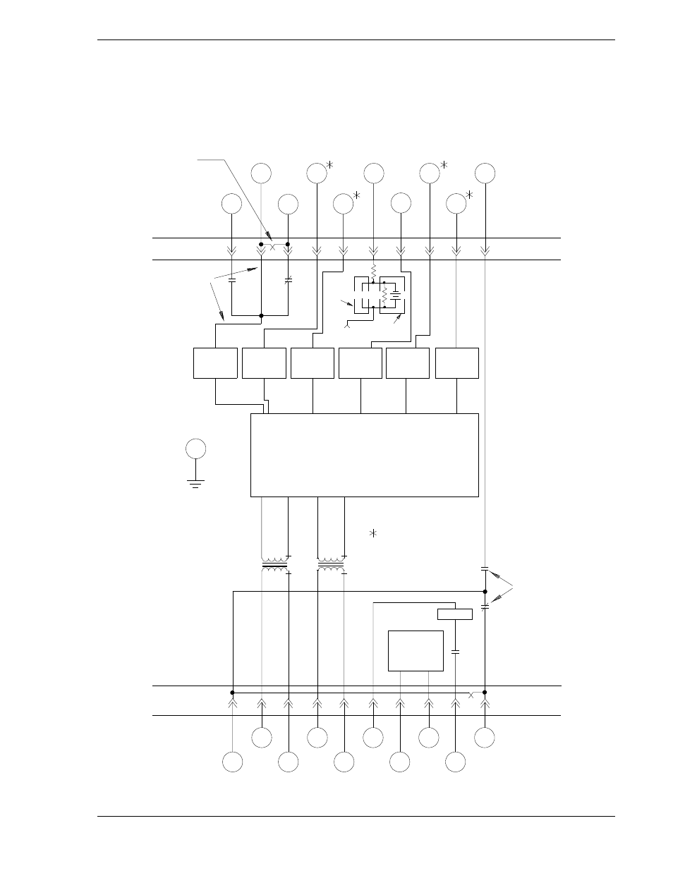
Typical internal connections are shown in Figure 4-8. Typical external connections are shown in Figures
4-9 through 4-12.
Figure 4-8. Internal Diagram
PADDLE
OPERATED
SHORTING
BARS
TERMINAL 19
WILL VARY
DEPENDING
ON OPTIONS
SYNC
OUT
OR
P.S.S.
NON-
ISOL.
CONT.
SENS.
AUX.
EXPAND
LINE
BUS
OPTO-
ISOLATOR
INTERNAL
CIRCUITRY
OPTO-
ISOLATOR
OPTO-
ISOLATOR
OPTO-
ISOLATOR
OPTO-
ISOLATOR
OPTO-
ISOLATOR
ISOL.
CONT.
SENS.
COM. TO
OPTO-ISOL.
Vctrl
J1
LL-DB
DL-LB
52b
Vctrl
DL-DB
LL-LB
11
12
13
14
15
16
17
18
19
20
EXTERNAL
CASE GROUND
TERMINAL
COM
10
9
EXTERNAL CONTACT
INPUTS FROM
RESISTOR MODULE
TARGET
VOLTAGE
MONITOR
OUT
SYNC
OUT
POWER
SUPPLY
D2819-03
08-29-02
LINE
COM
BUS
8
7
6
5
4
3
2
1
9170200990 Rev U
BE1-25 Installation
4-9