Figure 4-10. resistor module connections -11 – Basler Electric BE1-25 User Manual
Page 51
Advertising
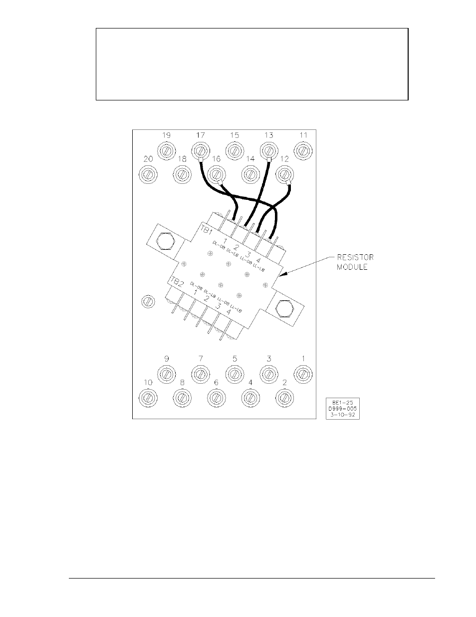
NOTE
The Resistor Module shown in Figure 4-10 is required for BE1-25 Sync-Check relays,
Voltage Monitor option 2-C, 2-U, or 2-V.
When the relay is to be projection mounted (see Figure 4-6), the Resistor Module must
be removed prior to installation. Once the relay is installed, the Module is then attached
to the rear of the mounting panel. The external contact inputs are then wired to the
Resistor Module at TB2.
Figure 4-10. Resistor Module Connections
9170200990 Rev U
BE1-25 Installation
4-11
Advertising