Table 2-1. location of controls and indicators -2 – Basler Electric BE1-25 User Manual
Page 26
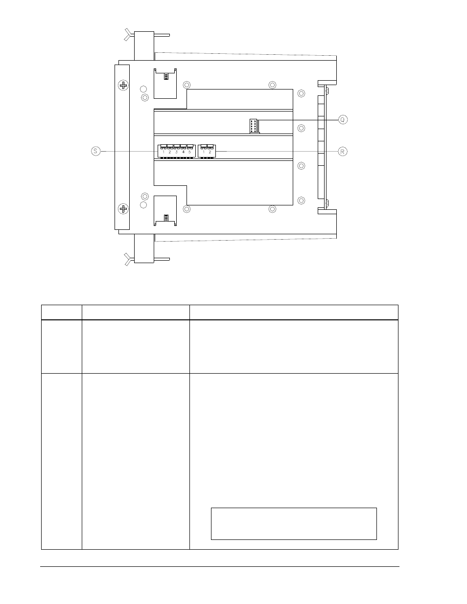
Figure 2-2. Location of Controls and Indicators (Interior View)
Table 2-1. Location of Controls and Indicators
Callout
Control or Indicator
Function
A
SYNC Indicator
Red LED lights when an in-sync condition has been of
sufficient duration to match the TIME DELAY setting.
Lighting of the LED coincides with closure of the Sync
Output contacts. The LED extinguishes when 52b opens
or the in-sync condition ceases.
B
TIME DELAY Selector
Thumbwheel switches establish the time delay between
sensing the desired in-sync condition and closing the
Sync Output contact. Time delay is in units of seconds or
of cycles, according to the option selected.
Option A6: Adjustable in 1-second increments over a
range of 01 to 99 seconds when multiplier switch (callout
D) is in the X 1.0 position. Alternatively, the range is 0.1 to
9.9 seconds with the multiplier switch in the X 0.1
position.
Option A7: Adjustable in 1-cycle increments from 1 to 99
cycles. The multiplier switch (callout D) is omitted.
NOTE
A setting of 00 will inhibit closing of the SYNC
output.
P0046-05
2-2
BE1-25 Controls and Indicators
9170200990 Rev U