Condition and mode switches, Condition and mode switches -2 – Basler Electric BE1-25 User Manual
Page 58
Advertising
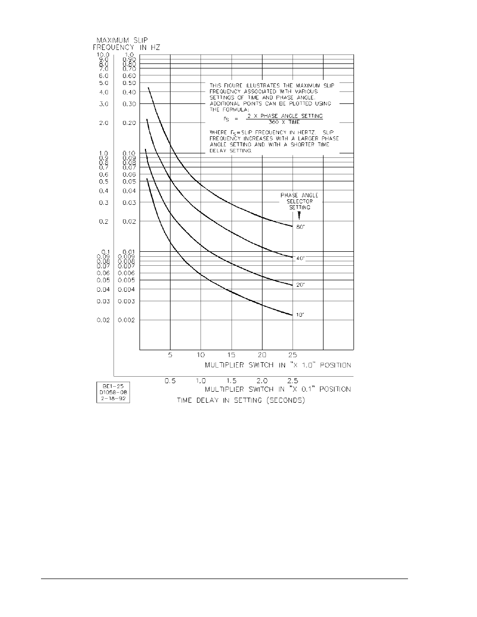
Figure 5-1. Maximum Slip Frequency versus Time Delay and Phase Angle Settings
Condition and Mode Switches
Detailed instructions and precautions for programming the Mode switches and Condition switches are
provided in Table 2-1, callouts R and S. The location of the switches is shown in Figure 2-2.
When output contacts of both Sync and Voltage Monitor functions are wired in parallel, the live line/live
bus Condition Switch No. 2 must be in OFF position. Otherwise, the Sync function will be overruled. If the
condition switches are external (option 2-C, 2-U, or 2-V), the external LL-LB switch should be omitted
when Sync and Voltage Monitor contacts are in parallel.
5-2
BE1-25 Testing
9170200990 Rev U
Advertising