Datatek DT-4180 User Manual
Page 17
9 4 8 0 , 4 1 8 0 , 4 2 8 0 , 4 2 8 4 4 0 0 0 X A U s e r
M a n u a l
04/09/09
17
4.3
INSTALLATION FOR DC OPERATION
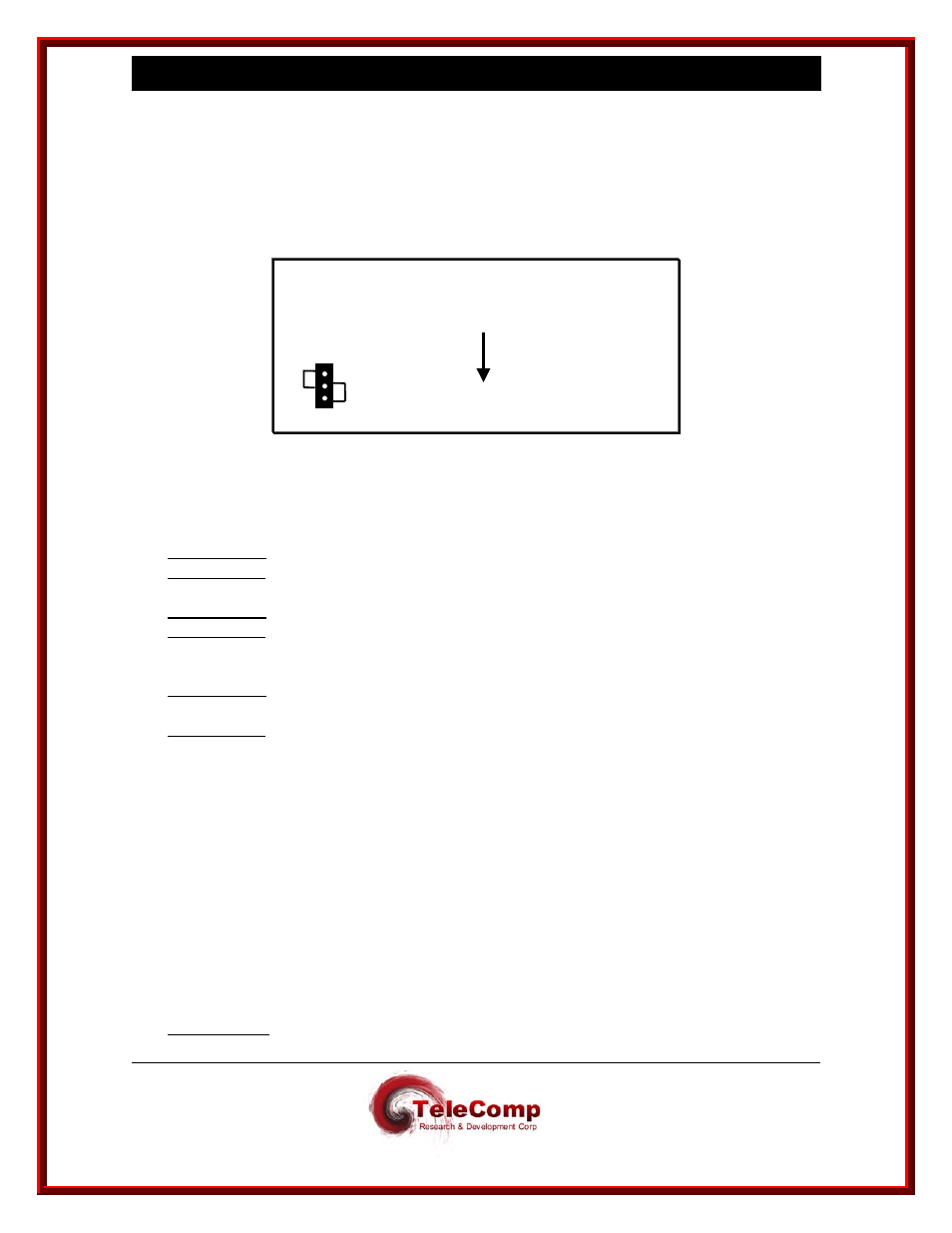
1. 4000XA and 4180 Power Strapping. The 4000XA and 4180 is factory configured for
115V AC usage. 48V DC operation requires a different jumper setting on the 4180
system board. Refer to the diagram below and perform the following steps:
JP2
5V
48V
4180
top down view
FRONT
Disconnect any power connectors from the unit. Remove the unit cover, exposing the
top portion of the system board. Locate the jumper connector (JP2) and move the
jumper to the 48v setting. Replace the unit cover.
2. Stand-Alone: Attach the provided feet to the bottom of the unit
Rack-Mount: Attach the mounting brackets to each side of the unit.
3. Stand-Alone: Fasten the strain relief to the side of the unit.
Rack-Mount: Fasten the strain relief to the unit rack-mount bracket.
4. Stand-Alone: Place the unit in the desired location, such as a shelf in a data
equipment rack.
Rack-Mount: Fasten the unit to a 19-inch equipment rack (using appropriate rack
screws) or use extension ears for a 23-inch rack.
5. Attach data transport cables – refer to section 4.5
6. Attach console cable by plugging one end of an RJ45-terminated twisted-pair data
cable into the unit console interface and the other into the port of the asynchronous
device that will be used to configure or manage the unit.
7.
Run 48V DC (return, -48, and ground) wires from a central source through the strain
relief clamp for DC wire stabilization. On the faceplate, attach the return, -48, and
ground wires to the return, -48, and ground connections, respectively, on the terminal
block labeled 48V DC.
8. Rack-Mount:
The Environmental Operating Range of 5 to 40 degrees C (41 to 124
degrees F) is necessary to maintain compliance with UL.