Vent configurations, Installation – Montigo 30FID Traditional User Manual
Page 13
Page 13
XG00516-
150204
I-Series Indoor Gas Fireplace
Installation
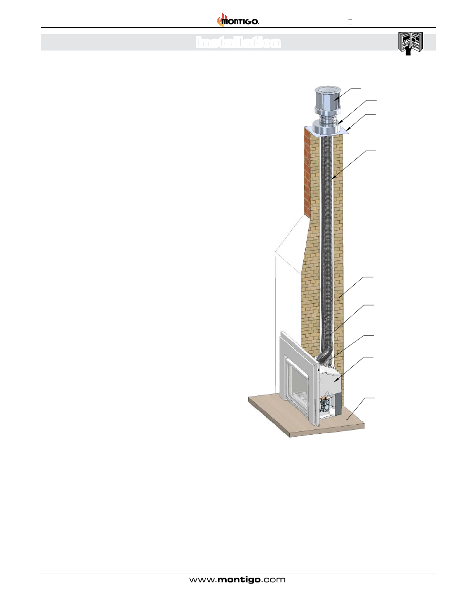
Figure 1 Sec.3
Vent Configurations
This appliance can only be vented vertically. The minimum vent
height measured from the floor under the unit to the bottom of the
termination is 10’. The maximum height that a vent can extend is
36’. This unit uses 3” x 3” Co-linear venting. This is a direct vent
unit and as such requires that both intake and exhaust vents are
connected and operational. Using existing chases as a partial vent
mechanism is not allowed. Due care is required to ensure that all
vent components are properly connected and sealed. Care must
also be taken when installing flashing or termination caps to make
sure that the structure of the building cannot be subject to water
penetration. Proper roofing and chimney finishing techniques
must be used.
Steps for vent connection
** Before installing the venting system, make sure that any dampers
or baffle plates in the fireplace are removed or do not present any
hindrance to your installation **
1). Determine the length of flex venting that will be required. Cut
2 lengths a couple of feet longer than you anticipate needing. The
length of these needs to be determined after the vent is stretched
out. Flex venting generally comes compressed and needs to be
stretch out to meet the lengths as specified.
2). From the roof, attach the Vent Lengths to the Adaptor. Don`t
forget to have the Flashing placed between the Flex Vent and the
Adaptor before attaching the Flex Vent.
3). Using commercial grade sealant around the perimeter of the
Collars of the Adaptor, use a minimum of 3 Tech screws in each Vent.
4). Install the Termination to the top of Adaptor. Use a minimum of
4 tech screws to attach the Termination to the Adaptor.
5). Feed the Flex Venting down the chimney until the Adaptor is
situated near the top of the Chimney. Use a commercial grade of
sealant between the Flashing and the Chimney top. Fasten the
Flashing to the top of the Chimney using a fastening method that
will properly secure the flashing permanently.
6). Attach the Adaptor to the top of the Flashing using 4 tech
screws. Seal around the perimeter of the Adaptor where it meets
the Flashing.
7). From inside the house check how long the vents protrude into
the Fireplace. Read the section on installation where fuel supply
pressure checking needs to be done. This procedure can be
done at this point by installing the venting to the appliance prior
to pushing the appliance into the fireplace cavity.
8). Once pre-installation steps have been completed, trim the vent
length to the correct length for installation. The Correct length will
leave the Flue Collar Slide Plate suspended around 18-19 inches
from the floor of the Fireplace.
9). Remove the Flue Collar Slide Plate from the appliance. Attach
both flex ends to the Flue Collar Slide plate. Use a commercial high
temp sealant around the Flue Collars on Flue Collar Slide Plate
before installing the Venting. Use a minimum of 3 tech screws to
properly secure the Venting to the Flue Collar Slide Plate.
** Make certain that the Exhaust and Intake Vents are connected
to the correct collars on the Flue Connection Plate. If they
are connected in reverse, this unit will not operate and re-
installation will be necessary. **
Termination 46DVA-VCH
Adaptor 46DVA-GK
Flex Liner VT15FL3
Hearth / Floor
Masonry Chimney
(Cut-away View)
Exhaust Flue
Intake Flue
Flashing
Fireplace Insert