Cable installation, Installation – Montigo 30FID Traditional User Manual
Page 32
Page 32
XG00516-
150204
I-Series Indoor Gas Fireplace
Installation
CPI [Continuous Pilot Ignition] / IPI [Intermittent Pilot
Ignition] Jumper Cable Installation
“Why bother with the CPI mode”?
There are several reasons why you may want to use the CPI mode.
Firstly, when a flue is cold, it can be problematic to light the appliance.
It takes a bit of time, particularly on tall vents to initialize vent action.
This can result in “lifting” or “ghosting” of the flames during the first
2-3 minutes of operation. You may also have instances where the
fireplace fails to light successfully, and will attempt to re-light the
second or third time depending on prevailing temperatures or altitude.
Another reason why you may want to leave it in CPI mode is that the
pilot keeps the system warm. During a “cold” start, there will normally
be condensation form on the inner glass surface of the door. This
condensation will quickly dry off however this condensation can tend
to run down the glass and cause some streaking. CPI will greatly
resolve that this issue. If the unit is placed in CPI mode in the winter
months, the energy it takes to run the pilot is partially recovered as
heat into the building, so it is not as energy wasteful as running a
pilot in the off season.
A connector is supplied with this unit that can be plugged into
the controller. This Jumper Cable enables the Remote Control to
operate the CPI / IPI switch and set the unit to operate in either
condition. CPI means “Continuous Pilot Ignition” or “Standing Pilot”
as most people would be familiar with. IPI means “Intermittent
Pilot Ignition”, which only initializes the pilot when you are going
to be using the appliance.
The difference of CPI and IPI:
IPI Mode: is a fuel saving mode in which the pilot is only used when
the main burner is on.
CPI: The Pilot runs continuously even when the main burner is off.
Installing the CPI Jumper Cable
1). Remove the Face Plate Front panel.
Figure 1 Sec.8
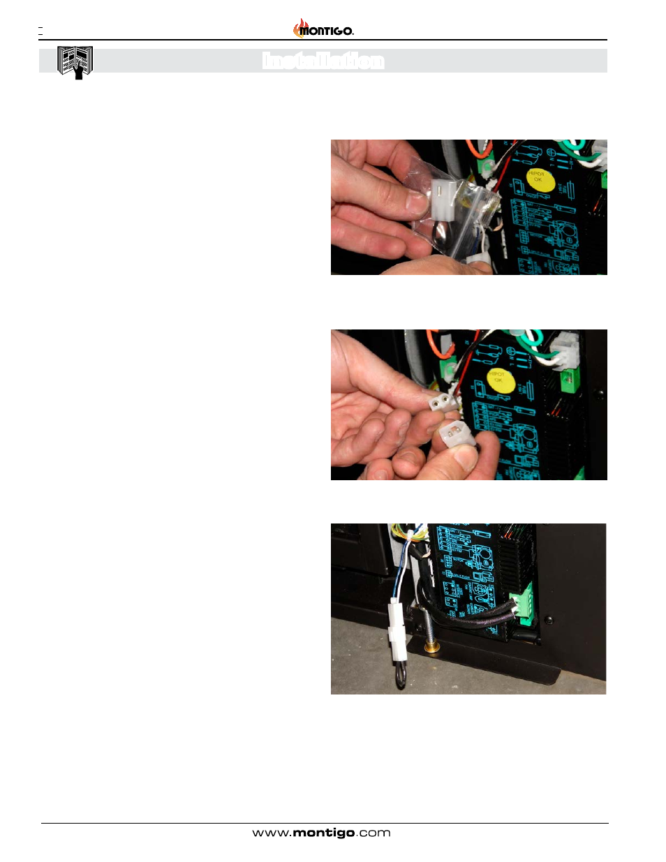
2). Remove the bag containing the Jumper Cable from the plastic
bag as shown. Remove the plastic bag from the unit.
Figure 2 Sec.8
3). Find the corresponding plug attached to the control wire harness.
Figure 3 Sec.8
4). Pack the Cable and Plug back around the control set and re-
install the Faceplate Front.
5). See operations section to turn remote into CPI mode.