Omnia Audio Omnia.ONE User Manual
Page 167
148
The Omnia ONE offers the ability to control several functions by means of trigger events (a trigger event is either a
physical contact closure or a virtual LiveWire GPIO event). Currently, presets may be selected, the primary and
secondary input sources may be selected, and the failover state may be set (forcing a switch to the secondary input)
or cleared (forcing a restore to primary input). Additionally, status information is available via the GPIO system
when any of the above events occur for any reason (such as front panel or remote control as well as due to trigger
event handling).
All of the above functionality is implemented via the LiveWire GPIO facilities that are part of LiveWire Routing
Protocol (LWRP). The functions are controlled by sending GPIO messages to "virtual" LiveWire GPO ports on the
Omnia, and status is monitored by monitoring virtual GPI ports. These ports are virtual in the sense that they do not
correspond to any physical output or input on the rear-panel, but instead initiate or report on actions that occur
within the unit. Outputs ports (GPO) are used to control the unit as they are an output from the network, and can
have a LiveWire GPI patched to them to make the GPI source control the Omnia. Input ports (GPI) are used to
report status from the unit as they are inputs to the network and can be patched to a LiveWire GPO to produce a
status output.
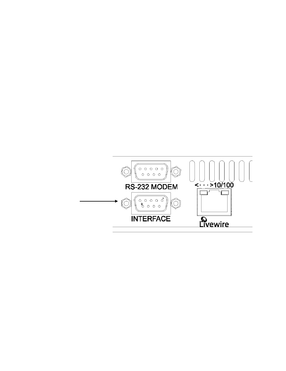
The GPI pins on the rear panel appear as a GPI port on the LiveWire network. Hence, this port can be patched to
any of the Omnia's GPO ports making it control the corresponding function (It could also be patched anywhere on
the LiveWire network instead of, or in addition to, using it locally). The "GPIO / Events" page on the Omnia's web-
based interface allows this to be done easily. It also allows other LiveWire GPI ports to be patched to the Omnia's
virtual GPO ports so that the corresponding function could be remotely controlled. Finally, it provides a means to
specify which presets can be selected by means of GPIO events.
Pin 1: +5VDC Out
Pin 2: In COM+
Pin 3: IN 1
Pin 4: IN 2
Pin 5: IN 3
Pin 6: IN 4
Pins 7,8,9: GND
Full GPIO control is available by directly using LWRP on a TCP connection to port 93 of the Omnia. See the
LWRP documentation for a description of this protocol itself. This document explains how the GPIO ports and the
pins within those ports are assigned on the Omnia ONE. In addition to the pin-based protocol, there is a stateless,
text command protocol using LWRP's GPIO "CMD:" syntax. This protocol is recommended instead of the pin-
based GPIO protocol when creating software remote control functions. The command descriptions are given below,
after the port and pin assignments.
•
The pin-based GPIO protocol was designed to be easy to use with raw contact closures (or independent
logic bits). It allows a pushbutton (or toggle switch) on each pin to be useful independently of the other buttons.
For example, a processing preset may be assigned to be selected by the "go-low" direction of each of the 5 pins in
the port. If this is done and five normally-open pushbuttons are connected between the pins of a controlling GPI
port and ground, each pushbutton will select a preset when pressed. If normally-closed pushbuttons are used, the
"go-high" direction of the pins would have to be used to create the same effect. One would not typically assign both
the go-low and go-high directions of the same pins at the same time. An exception might be to use a single toggle
switch on a single pin to select between 2 presets, one for each direction. A little thought will show that using
multiple toggle switches in this manner will lead to problems selecting the desired preset without going through
intermediate presets.