Vcm, vcm-x & vcb-x controllers, Vcb-x controllers vcb-x confi guration, Smts ii technical guide – Orion System System Manager TS II In-House User Manual
Page 43
SMTS II Technical Guide
VCM, VCM-X & VCB-X Controllers
43
VCB-X Controllers
VCB-X Confi guration
VCB-X Confi guration
Touch the
< Confi guration>
button to access the Confi gu-
ration Setpoints Screens.
For screens that contain radio buttons, touch the radio
button next to your selection. For screens with square
buttons, touch one or more square buttons to make your confi guration
selections for the unit.
Check this Box for Celsius Temperature Scaling—
Touch
the square button to select Celsius Temperature Scaling. Default
is
Fahrenheit.
Installed Sensors
Touch the square button to select the sensors that are installed:
Carbon Dioxide Sensor Installed
Suction Pressure Sensor Installed
Communicating Indoor Sensor Installed
—This is the
E-BUS Digital Room Temperature Sensor or Digital
Temperature and Humidity Sensor.
Communicating Outdoor Sensor Installed
—This is
the E-BUS Outdoor Air Temperature and Humidity Sensor.
Config
Installed Expansion Boards and Modules
Touch the square button to select the Expansion Board(s) and Modules
that are installed. The available selections are as follows:
Main Expansion Board Installed
—This is the
EM1 Module. The following IO is available on EM1:
VAV Capabilities
Water Temperature
Building Pressure
Hood On/Off
Head Pressure Control
Proof of Flow
Return Air Temperature
Condenser Control
Remote Forced Occupied
Water Source Heat Pump Monitoring
Modulating Chilled Water
ReHeat Expansion Board Installed
—This is the
MHGRV-X
Controller.
Mod Gas Expansion Board Installed
—This is the
MODGAS-X
Controller.
12 Relay Expansion Board Installed
—This is the
E-BUS 12 Relay Expansion Module.
DPAC/ Remote Control Expansion Installed
—This is
the EM2 Expansion Module.
PreHeater Expansion Installed
—This is the
PREHEAT-X Controller.
HVAC Mode Enable Source
Touch the radio button to select the Temperature Sensor/Application
that will determine the Heating, Cooling, or Vent Mode of operation.
Default is Single Zone VAV. The available selections are as follows:
Single Zone VAV
—Recirculating unit using the Space
Temperature Sensor to determine the mode of operation.
Heating and Cooling are controlled to a Leaving Air
Setpoint. Space Temperature resets the Supply Fan VFD
speed to maintain the Space Temperature. Modulating
Heating and Cooling must be used for VAV operation.
Can be confi gured for CAV Heating using staged Heat.
Space Temperature
—Typical recirculating unit using a
Space Temperature Sensor to determine the Heating,
Cooling, and Vent Modes of operation.
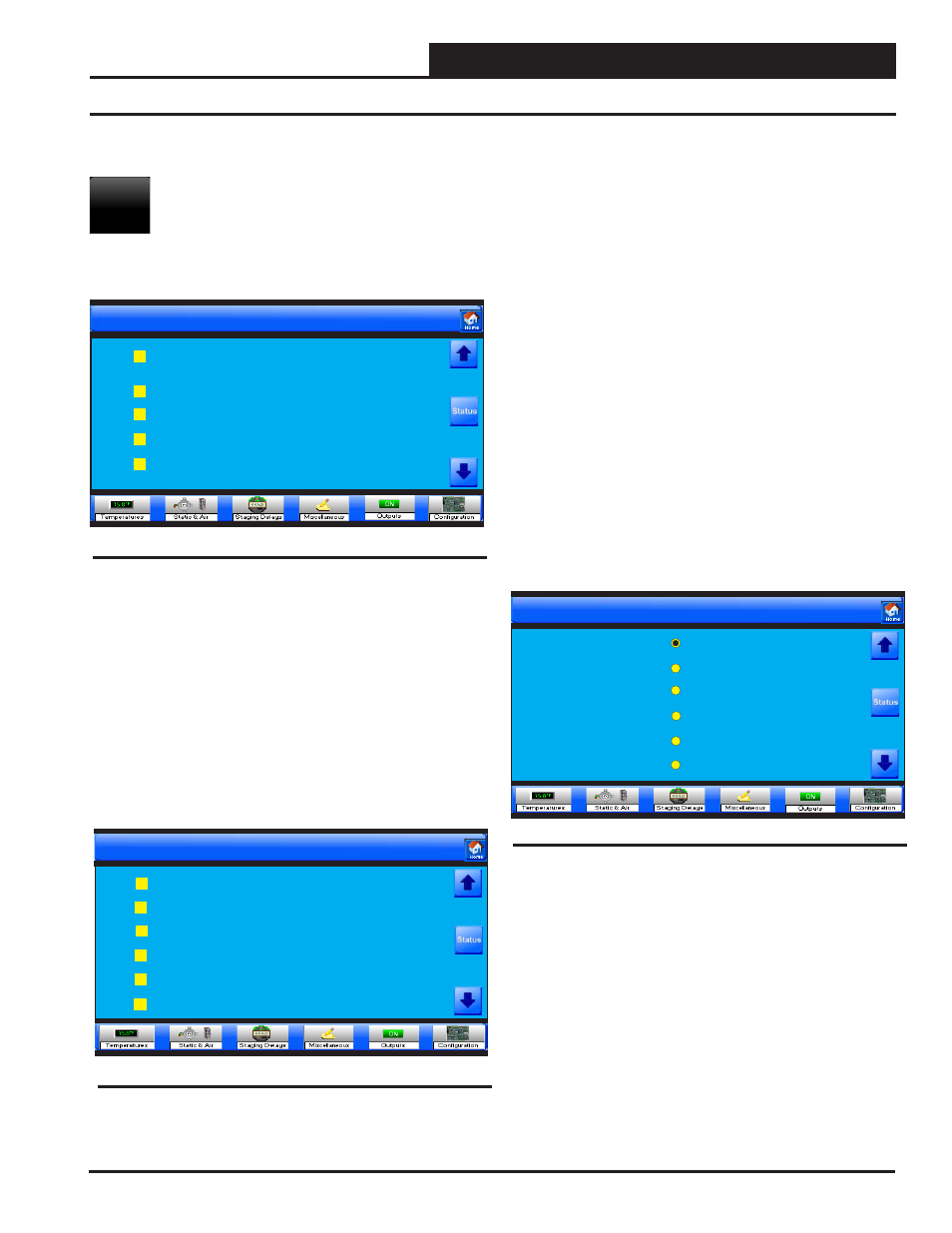
Setpoints for Unit 0001
Configuration
Page 1 of 19
Check this Box for Celsius Temperature Scaling
Carbon Dioxide Sensor Installed
Suction Pressure Sensor Installed
Communicating Indoor Sensor Installed
Communicating Outdoor Sensor Installed
Figure 73: VCB-X Relay Confi guration Screen 1
Setpoints for Unit 0001
Configuration
Page 2 of 19
Main Expansion Board Installed
Re-Heat Expansion Board Installed
Mod Gas Expansion Board Installed
12 Relay Expansion Board Installed
DPAC / Remote Control Expansion Installed
PreHeater Expansion Installed
Figure 74: VCB-X Relay Confi guration Screen 2
Setpoints for Unit 0001
Configuration
HVAC Mode Enable Source
Single Zone VAV
Space Temperature
Outdoor Air Temperature
Supply Air Cooling Only
Return Air Temperature
Space Temp with High OA Content
Page 3 of 19
Figure 75: VCB-X Relay Confi guration Screen 3