Vcm, vcm-x & vcb-x controllers, Vcb-x controllers, Vcb-x static & staging delay setpoints – Orion System System Manager TS II In-House User Manual
Page 56: Smts ii technical guide 56, Zone
Zone
Zone
VCM, VCM-X & VCB-X Controllers
SMTS II Technical Guide
56
VCB-X Controllers
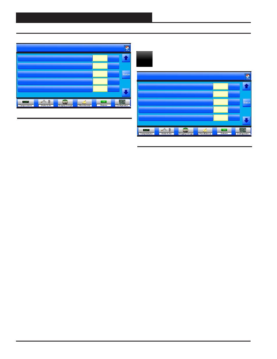
Setpoints for Unit 0001
Outdoor CFM Intake Area
0.00
Sq Ft
Exhaust CFM Area
Supply CFM Area
0.00
0.00
Static & Air Setpoints
Sq Ft
Sq Ft
Return CFM Area
Page 4 of 4
Sq Ft
0.00
Figure 106: VCB-X Static & Air Setpoints Screen 4
Outside CFM Intake Area
For the controller to properly calculate the Outside Air CFM, you need
to enter the inside area (sq. ft.) of the Outdoor Air Duct/Damper. When
measuring the Outdoor Air Damper area, be sure to measure the inside
dimensions of the damper. The more accurate the measurements, the
more accurate the CFM reading will be. This value needs to be accu-
rate to 2 decimal places. High limit = 200 sq. ft.; Low limit = 0 sq. ft.;
Default = 0 sq. ft.
Exhaust CFM Area
For the controller to properly calculate the Exhaust Air CFM, you need
to enter the inside area in square feet of the Exhaust Air duct/damper.
When measuring the Exhaust Air damper area, be sure to measure the
inside dimensions of the damper. The duct size needs to be accurate to
two decimal places. The more accurate the measurements, the more
accurate the CFM reading will be. High limit = 200 sq. ft.; Low limit =
0 sq. ft.; Default = 0 sq. ft.
Supply CFM Area
For the controller to properly calculate the Supply Air CFM, you need
to enter the area in square feet of the Supply Air Duct/Damper. When
measuring the Supply Duct Damper area, be sure to measure the inside
dimensions of the damper. The more accurate the measurements, the
more accurate the CFM reading will be. This value needs to be accurate
to 2 decimal places. High limit = 200 sq. ft.; Low limit = 0 sq. ft.
Return CFM Area
For the controller to properly calculate the Return Air CFM, you need
to enter the area in square feet of the Return Air Duct/Damper. When
measuring the Return Air Damper area, be sure to measure the inside
dimensions of the damper. The more accurate the measurements, the
more accurate the CFM reading will be. This value needs to be accu-
rate to 2 decimal places. High limit = 200 sq. ft.; Low limit = 0 sq. ft.;
Default = 0 sq. ft.
Staging Delays Setpoints
Touch the
< Staging Delays>
button to access the Staging
Delays Setpoint Screens.
Cooling Stage Up Delay Time
This is the amount of time that must elapse between each Compressor
activation to prevent all Compressors from activating at the same time
due to large cooling demands. High limit = 15 minutes; Low limit = 3
minutes; Default = 3 minutes.
Cooling Stage Down Delay Time
This is the amount of time that must elapse between each Compressor
deactivation to prevent all Compressors from deactivating at once as
the cooling demand decreases. High limit = 15 minutes; Low limit = 1
minute; Default = 1 minute.
Cooling Minimum Run Time
This is the minimum amount of time the Compressors must remain on
once they have been activated. This overrides the Stage Down Delay if
that is not as long as this delay. High limit = 15 minutes; Low limit = 5
minutes; Default = 5 minutes.
Cooling Minimum Off Time
Once a Compressor has been staged back off, it must remain off for this
amount of time to prevent short cycling. High limit = 15 minutes; Low
limit = 3 minutes; Default = 3 minutes.
Mod Cooling Time Period
The Mod Cooling Time Period is the delay before another Modulating
Cooling Signal increase or decrease can be made and is user-adjustable.
Short Mod Cooling Time Periods may cause hunting of the Modulat-
ing Cooling Signal. This is the rate at which the Modulating Cooling
Signal is calculated. High limit = 240 seconds; Low limit = 5 seconds;
Default = 30 seconds.
VCB-X Static & Staging Delay Setpoints
Staging
Setpoints for Unit 0001
Cooling Stage Up Delay Time
Cooling Minimum Off Time
Mod Cooling Time Period
3
3
30
Min
Cooling Stage Down Delay Time
Cooling Minimum Run Time
1
5
Staging Delays
Min
Min
Min
Min
Page 1 of 5
Figure 107: VCB-X Staging Delay Setpoints Screen 1