Components and wiring, Mounting, wiring, initializing, and updating – Orion System System Manager TS II In-House User Manual
Page 5
SMTS II Technical Guide
Components and Wiring
5
Mounting, Wiring, Initializing, and Updating
Environmental Requirements
The System Manager TS II needs to be installed in an environment that
can maintain a temperature range between 14°F and 158°F with less
than 90% RH levels (non-condensing).
Mounting
The System Manager TS II is housed in a plastic enclosure designed
for mounting in hollow drywall construction or a control panel cover
with the fl ush wall mount version (shown in Figure 3) or on a concrete,
brick, or other solid wall surface with the surface mount version (shown
in Figure 4).
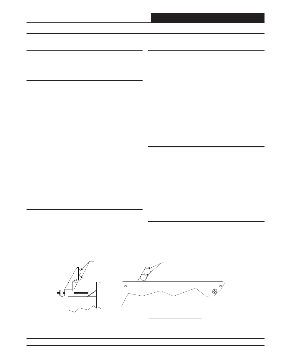
The fl ush wall mount version has integral wingnut paddles that are tight-
ened after installation to grip the drywall and hold the System Manager
TS II in place. For mounting in a control panel cover or other thin mate-
rial, (4) adhesive backed rubber pads are provided to assist in securing
the System Manager TS II into the cutout in the panel. These pads are
applied to the wingnut paddles to provide a non-slip mounting against
the panel’s sheet metal surface. See Figure 2 for pad placement details.
The surface mount version is designed to be installed in a double duplex
outlet box (by others). Both mounting styles of the System Manager
TS II feature an integral, magnetically-secured face plate which can be
easily removed for reset of the display when required.
The System Manager TS II should be mounted at approximately eye
level to allow for ease of programming and reading of the display. The
System Manager TS II is typically mounted in the building manager’s
or superintendent’s offi ce or in an equipment room, but is also quite
suitable for mounting in any location or with most decors.
Care
The System Manager TS II should be cleaned with a soft, dust-free cloth.
Do not use any liquid to clean your System Manager TS II. You should
press the
< Suspend>
button located behind the cover to temporarily
freeze the touch pad before you attempt to clean your screen. See the
Troubleshooting section on page 70 for details.
Wiring
The System Manager TS II is connected to the local communications
loop of the Orion system via 18 AWG 2-conductor, twisted pair with
shield wire connected to the T, SHLD & R communication terminals on
the back of the System Manager TS II. The communications wire used
can be either our WattMaster # WR-LL-WG-18 communications wire
or Belden #82760 wire or its equivalent.
The System Manager TS II also requires that 24 VAC (6 VA) power be
supplied (by others) to its + and – wiring terminal located on the back
of the System Manager TS II.
See Figures 5-8 for wiring details. These wiring diagrams depict wiring
the System Manager TS II to the VCM-X Controller, VCM Controller,
VCB-X Controller and VAV/Zone Controller. The System Manager TS II
can also be wired to the local loop terminals on the MiniLink PD, Power
Comm Board, or any other add-on controller’s local loop terminals. It
will still require a transformer to be wired as shown in Figures 5, 6 & 7.
Dipswitch and Jumper Settings
If you are using a VCB-X Controller set at high speed, Dipswitch OPT1
should be set to ON; in all other instances, it should be set to OFF. As of
April 2014, Dipswitch OPT4 should be set to ON by default. Previous
versions should be set to OFF. If you see your screen is not centered
correctly, switch OPT4 to the opposite position. Dipswitches OPT2
and OPT3 should always be set to OFF. See Figures 5-8, pages 8-11
for details.
If you have a Stand-Alone system (no CommLink or MiniLink, the
TERM Jumpers must be ON. For applications with CommLink(s) and/
or MiniLink(s), the TERM Jumpers must be OFF. See Figures 5-8,
pages 8-11 for details.
Technical Support
Call (866) 918-1100 to talk to a WattMaster Controls Technical Support
Representative. Support is available Monday through Friday, 7:00 AM
to 5:00 PM central standard time.
Front View (Cover Removed)
Left Side View
USE
4
Place (2)
On Each Paddle Arm
As Shown When Mounting In Sheet Metal
Panel Or Other Thin Mounting Material. Pads
Are Not Required For Drywall Mounting
Rubber Pads
Rubber Pads
Figure 2: System Manager TS II - Control Panel Mounting Pad Placement Detail ( Flush Wall Mount)
Revised 4/21/14