REMKO Multi-talent User Manual
Page 49
Designation
Value range
Programming
Output/level
00–9950 kW
WE 1 level 1 = 50
WE 2 level 1 = 1
WE 3 level 1 = 1
continue with key next to "End"
MF 1 function
00-36
00
T-MF 1 target
-20°C-90°C
(----)
MF 1 Hyst
2K-10K
(----)
MF 1 Hyst Off
2K-10K
(----)
MF 2 function
00-36
18
T-MF 2 target
-20°C-90°C
(----)
MF 2 Hyst
2K-10K
(----)
MF 2 Hyst Off
2K-10K
(----)
MF 3 function
00-36
10
T-MF 3 target
-20°C-90°C
(----)
MF 3 Hyst
2K-10K
(----)
MF 3 Hyst Off
2K-10K
(----)
MF 4 function
00-36
02
T-MF 4 target
-20°C-90°C
(----)
MF 4 Hyst
2K-10K
(----)
MF 4 Hyst Off
2K-10K
(----)
F15 function
00-08
07
E1 function
00-03
02
E2 function
00-03
03
Sensor
1k/5k sensors
5k sensors
Designation
Value range
Programming
BUS code BM
Off, 00-15
Off
Language
D/GB/F/NL/E/I
D (German)
Terminal address
On/Off
On
Time
0-24
Set time
Date
Year, month, day
Set date
BUS code 1
00-15
01
BUS code 2
00-15
02
System selection
---/01-12
02
Regulator type
00-06
06
WE 1 type
00-09
07
WE bus
00-05
05
Gradient
On/Off
Off
WE 2 type
00-22
01
WE 2 tank
00-03
00
WE 3 type
00-09
01
WE 4 type
00-09
00
Buffer type
00-02
00
Cooling mode
Off/On
Off
HC1 function
Standard, T-feed
const, swimming
pool, WW,
return
Standard
HC2 function
see HC1
Standard
0000
F17
V
A
B
AB
M
M
F9
1)
2)
2)
l/h
Tmax
3)
F8
F6
F11
F5
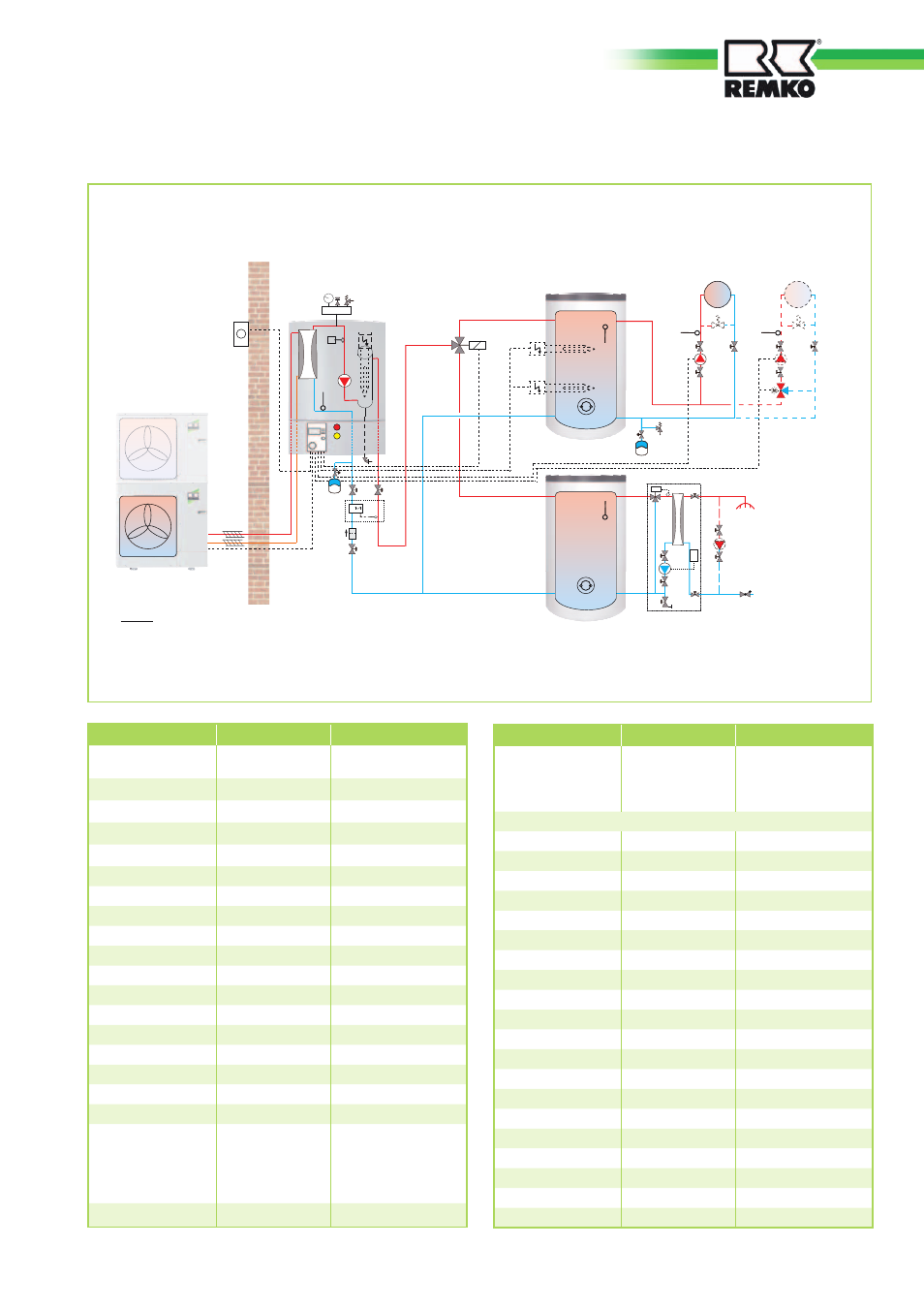
Hydraulic diagram for the heat pump assembly 2 (only for CMF 80/140)
Functions: Heating and hot water,
monoenergetic operating mode
“System selection 2”
Outdoor unit
Indoor unit
CMF 80/140
Process water
Storage tank
HPS 500
Heating/cooling
water-Storage tank
KPS 300
Heating circuit 1 Heating circuit 2
4)
Notes:
1) Recommended location for heating meters. These are not included in REMKO's scope of delivery.
We recommend a set-up with a flow volume of 2.5 m
3
/h.
2) Heating circuit circulation pump(s) not included in REMKO's scope of delivery. We recommend the use of high-efficiency circulation pumps.
3) Option: As many as 2 additional submersible electric heating elements can be mounted in the hot water storage tank (an external
protector is necessary on-site).
4) If the surface heating is the only heat distribution system, it automatically becomes a heating circuit 1. A mixer is not necessary in this case!
Taps
CW inlet
Fresh water station
Sample hydraulic diagram for system selection 2
49