REMKO Multi-talent User Manual
Page 53
F9
0000
F14
0000
1)
V
F17
A
B
AB
F6
F8
F12
A
B
AB
M
M
4)
2)
l/h
Tmax
F5
Designation
Value range
Programming
Output/level
00 – 9950 kW
WE 1 level 1 = 50
WE 2 level 1 = (---)
WE 3 level 1 = 1
continue with key next to "End"
MF 1 function
0 0 - 3 6
0 0
T - MF 1 target
- 2 0 °C - 9 0 °C
( ---- )
MF 1 Hyst
2 K - 1 0 K
( ---- )
MF 1 Hyst Off
2 K - 1 0 K
( ---- )
MF 2 function
0 0 - 3 6
18
T - MF 2 target
- 2 0 °C - 9 0 °C
( ---- )
MF 2 Hyst
2 K - 1 0 K
( ---- )
MF 2 Hyst Off
2 K - 1 0 K
( ---- )
MF 3 function
0 0 - 3 6
1 0
T - MF 3 target
- 2 0 °C - 9 0 °C
( ---- )
MF 3 Hyst
2 K - 1 0 K
( ---- )
MF 3 Hyst Off
2 K - 1 0 K
( ---- )
MF 4 function
0 0 - 3 6
2 3
T - MF 4 target
- 2 0 °C - 9 0 °C
( ---- )
MF 4 Hyst
2 K - 1 0 K
5.0K
MF 4 Hyst Off
2 K - 1 0 K
2.0K
F15 function
0 0 - 0 8
0 7
E 1 function
0 0 - 0 3
0 2
E 2 function
0 0 - 0 3
0 3
Sensor
1k/5k sensors
5k sensors
Designation
Value range
Programming
BUS code BM
Off, 00-15
Off
Language
D/GB/F/NL/E/I
D (German)
Terminal address
On/Off
On
Time
0-24
Set time
Date
Year, month, day
Set date
BUS code 1
00-15
01
BUS code 2
00-15
02
System selection
---/01-09
05
Regulator type
00-06
06
WE 1 type
00-09
07
WE bus
00-05
05
Gradient
On/Off
Off
WE 2 type
00-22
00
WE 2 tank
00-03
00
WE 3 type
00-09
01
WE 4 type
00-09
00
Buffer type
00-02
00
Cooling mode
Off/On
Off
HC1 function
Standard, T-feed
const, swimming
pool, WW,
return
Standard
HC2 function
see HC1
Standard
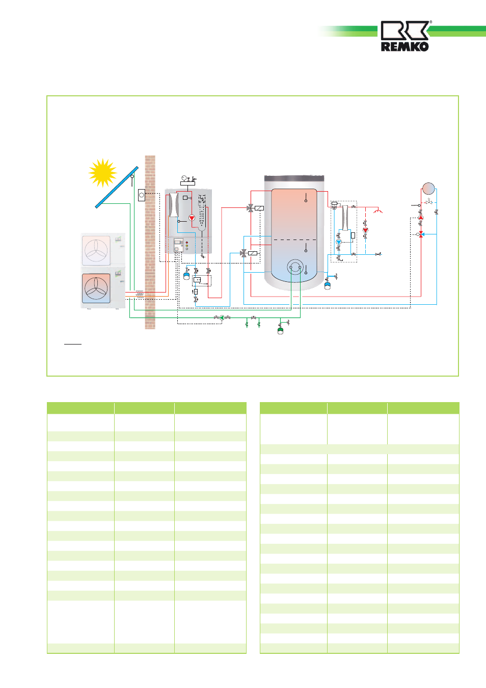
Outdoor unit
Indoor unit
CMF 80/140
Multi purpose
storage tank
MPS 1000
Notes:
1) Heating circuit circulation pump(s) not included in REMKO's scope of delivery. We recommend the use of high-efficiency circulation pumps.
2) We recommend, because of possible high temperatures - caused by the solar plant, to always connect the heating circuit
over a 3-way mixer.
3) If a circulation pump is installed, it must be controlled separately.
Taps
CW inlet
Fresh water station
Hydraulic diagram for the heat pump assembly 5 (only for CMF 80/140)
Functions: Heating, hot water and solar
monoenergetic operating mode
“System selection 5”
Sample hydraulic diagram for system selection 5
Heating
circuit
53