REMKO Multi-talent User Manual
Page 65
Please also note the connection diagrams or the electrical circuit diagrams for the installed heat pump.
These are found in the respective installation manual.
NOTE
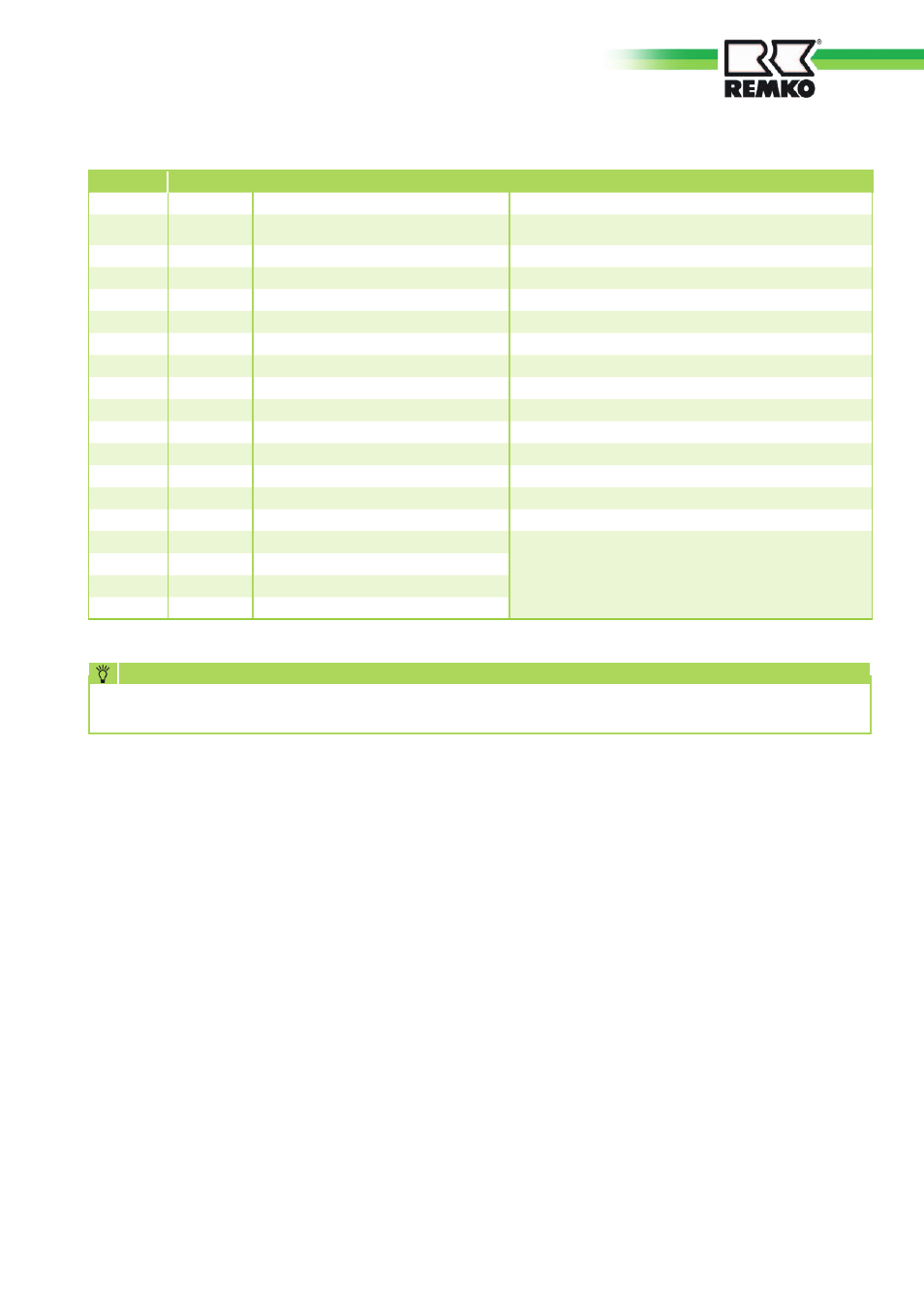
Terminal
Sensor no.
Description
Note
1
F9
External sensor
2
F8
Collector sensor (collective supply)
Heating control sensor
Heating control sensor. Must be located in accordance with the
system diagram!
3
F6
Hot water sensor
4
F5
Supply sensor HC 2 (mixer circuit)
5
F3
FBR-2
Analog remote control (only for HK1)
6
F2
FBR-2
Analog remote control (only for HK1)
7
F1
Sensor storage tank bottom
Reference sensor solid-fuel boiler
8
F11
Supply sensor WP or HC 1
HC 1 is a direct heating circuit
9
F12
Sensor storage tank bottom
Reference sensor solar or solid-fuel boiler
10
F13
not assigned
11
F14
Sensor solar collector or solid-fuel boiler
Pt 1000
12
F15
Flow meter
Impulse input
13
F17
Return sensor (cooling control sensor)
14
eBUS +
Signal output 0-10 V
Modulation depth (target output in %)
15
eBus -
Signal output 0-10 V
Modulation depth (target output in %)
16
CAN-Bus H
Data bus for connecting to other heat pumps managers and / or
digital remote controls
17
CAN-Bus L
18
CAN-Bus -
19
CAN-Bus +
Remko specific contact layout for the circuit board inputs
Setting of the DIP switches
(ADR)
DIP switches 1-4:
The DIP switches 1-4 serve for
the setting of the controller
address. Normally the standard
address is set to 01. On the
other hand, if multiple controllers
(heat pump manager) are in the
system (switched in combination
through the CAN-BUS loop),
each individual controller must
be issued a separate controller
address. The address must then
be adopted in the corresponding
display/control element (BM-T
"Terminal"). It is possible to assign
a maximum 16 different addresses
- in other words the use of up to
16 controllers. The assignment
of the DIP switch position for the
controller address can be found
directly in the "Solder side view"
connection diagram.
DIP switch 5:
Not assigned
DIP switch 6:
DIP switch 6 serves as a BUS load
resistor. The BUS load resistor must
be set once in the bus system.
DIP switch 6 --> OFF: The load
resistor is not set.
DIP switch 6 --> ON: The load
resistor is set.
LED displays
Green LED blinking: no BUS
connection
Green LED continuous: BUS-connection
present
Red LED blinking: Error
RESET to factory setting
The heat pump manager can be
reset to the factory setting.
For this purpose, proceed as fol-
lows:
1. Voltage OFF
2. Block DIP switch 1
3. Voltage ON
4. Reset DIP Switch 1
Note: Step 4 must take place
within 3 seconds of Step 3. The
loading of the factory setting was
successful if the LEDs flicker for 1
second during Step 4.
65