2 analog inputs – Sensoray 2600 User Manual
Page 36
2600 Family Instruction Manual
31
Chapter 6 : Model 2608 Analog I/O Module
“AOUT7,” which correspond to analog output channels 0
through 7, respectively.
The connector pinout is identical for all eight AOUT channels:
6.4.2 Analog Inputs
Each AIN channel is provided with a 10-pin header—called
the input programming block, or IPB—that is designed to
accept hardware programming shunts. Various signal
conditioning options are enabled by installing shunts on the
IPB as described in the following sections.
6.4.2.1 Thermocouple Shunts
Each IPB has options for installing either one or two shunts for
TC support. A shunt should always be installed at pins 5-6
when the affiliated AIN channel will be connected to a TC.
This will prevent the TC’s common-mode voltage (CMV)
from exceeding the maximum specified input CMV for the
AIN channel, and it provides a low impedance current path to
ground for RF noise.
To enable open-TC detection, install a second shunt at pins
7-8. This will force the AIN channel to return a large, positive
digitized value in the event of an open-circuit failure at the
TC’s hot junction. If this shunt is not installed, the returned
digitized value will be indeterminate in the case of an open TC.
6.4.2.2 4-20mA Termination Shunts
When an AIN channel is interfaced to a 4-20mA current loop,
the IPB may be programmed to insert a 500 ohm, 1% resistor
into the loop to convert the loop current to a voltage. Install a
shunt at pins 9-10 to enable this option.
6.4.2.3 Power Distribution Shunts
In many applications, it is necessary to supply operating power
to devices that are connected to AIN channels. The IPB may
be programmed to route either 24VDC or 10VDC to an
external device via the associated AIN channel’s terminal
block. The selected voltage is routed to the channel’s “Pwr”
terminal.
Install a shunt on the IPB at pins 3-4 to route 24VDC to the
Pwr terminal. Install a shunt on the IPB at pins 2-4 to route
10VDC to the Pwr terminal.
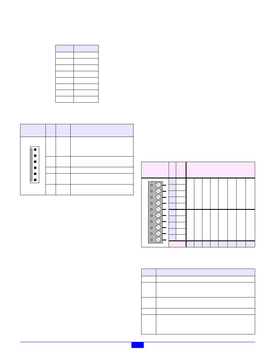
6.4.2.4 Terminal Blocks
Eight 10-pin pluggable terminal blocks (TBs) provide all
connections required by the sixteen AIN channels. Each TB
provides connections for two adjacent AIN channels, as shown
in Table 12.
Each AIN channel has five signals, as detailed in Table 13.
Table 10: AOUT Connectors
Chan
Connector
AOUT0
P1
AOUT1
P2
AOUT2
P7
AOUT3
P8
AOUT4
P9
AOUT5
P10
AOUT6
P15
AOUT7
P16
Table 11: Pinouts of AOUT Connectors
Layout
(top view)
Pin Name
Function
1
Shld
This may be connected to a cable shield,
but the shield conductor must be left
disconnected at the remote end of the
cable in order to avoid ground loops.
2
Out
Analog output signal that supplies current
to the load.
3
Sense
Analog output remote sense.
4
Com
Analog output current return. The load is
connected between this pin and Out.
5
Pwr
Optional power output, either 24VDC or
10VDC.
1
2
3
4
5
6
Table 12: Pinouts of AIN Terminal Blocks
Layout
(top view)
P
in
N
o
.
F
u
n
c
.
Channel
1
Pwr
1
3
5
7
9
11
13
15
2
Shld
3
Ain+
4
Ain-
5
Com
6
Pwr
0
2
4
6
8
10
12
14
7
Shld
8
Ain+
9
Ain-
10
Com
TB:
P6 P5 P4 P3 P11 P12 P13 P14
Table 13: AIN Signals
Name
Function
Pwr
Optional power output, either 24VDC or 10VDC.
Shld
This may be connected to a cable shield, but the shield conductor
must be left disconnected at the remote end of the cable in order to
avoid ground loops.
Ain+
Positive sense input. The differential input signal is applied to
Ain+ and Ain-.
Ain-
Negative sense input.
Com
Analog ground reference. If connecting to an isolated signal
source (e.g., isolated power supply, battery, etc.) this should be
connected to Ain+ or Ain- to prevent excessive common mode
voltages. This signal may also be used as a current return for Pwr.
1
2
3
4
5
6
7
8
9
1
0