1 introduction, 2 hardware configuration, 1 iom network connector – Sensoray 2600 User Manual
Page 41: 2 interlock power connectors
2600 Family Instruction Manual
36
Chapter 7 : Model 2610 Digital I/O Module
Chapter 7: Model 2610 Digital I/O Module
7.1 Introduction
The model 2610 is a smart I/O module (IOM) that has 48
programmable digital I/O (DIO) channels, numbered 0 to 47.
The module’s microcontroller, which provides I/O services to a
remote client, communicates with the client by means of a
standard Category-5 STP/UTP cable over an optically isolated,
asynchronous serial interface.
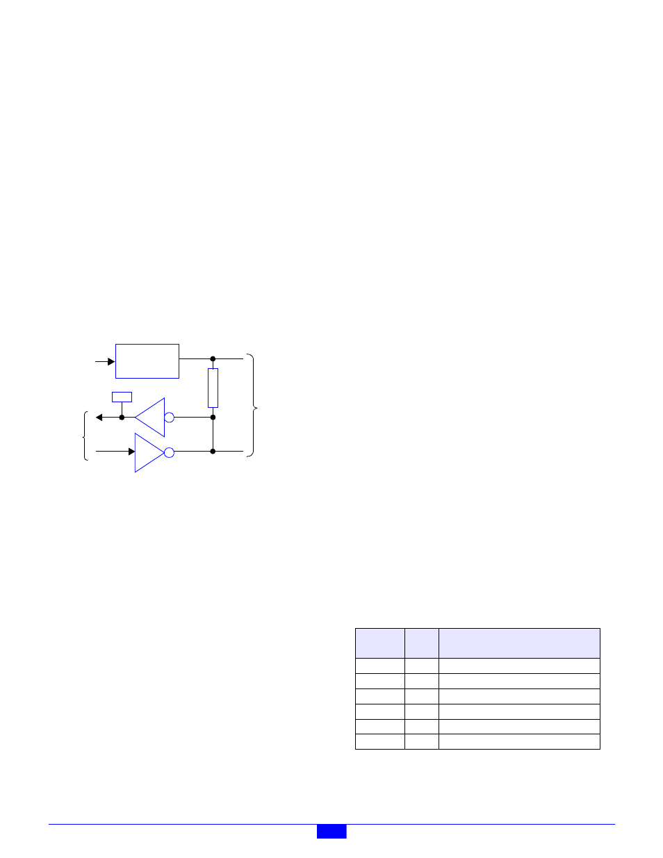
As shown in Figure 34, each channel consists of an active-low,
open-collector driver, a pull-up resistor and an active-low
receiver. A shunt programming matrix enables one of six
possible external power sources to supply power to the
channel. For simplicity, some circuitry is excluded from the
block diagram, including a diode that suppresses induced EMF
from inductive loads.
Figure 34: DIO Channel Block Diagram
The client can program and read back the state of each
channel’s output driver, and it can acquire the debounced state
of each channel’s physical signal. The microcontroller
debounces all acquired channel states by means of a 10
millisecond software debounce filter. In addition, 32 of the
DIO channels have the ability to autonomously generate PWM
output signals at a rate and duty cycle specified by the client.
Each DIO channel includes an LED indicator that lights when
the channel is active. The indicator lights regardless of
whether the channel is driven by an external signal source or
by the channel’s output driver.
On-board connectors enable direct connection to field wiring
without the need for intermediate terminal blocks. Each
connector, which uses a standard RJ-12 modular jack, includes
connections for three DIO channels to support direct wiring to
devices that require the services of multiple DIO channels.
Integral support is provided for system interlock circuits and
multiple DIO power supply voltages. Each DIO channel may
be independently powered from any of up to six external power
sources.
The communication interface between the client and the
on-board microcontroller is optically isolated to ensure
error-free operation in demanding industrial environments.
7.2 Hardware Configuration
The DIO module is configured by installing programming
shunts and connecting various cables to the module as
described in this section.
7.2.1 IOM Network Connector
A single RJ-45 connector, J49, is used to connect the DIO
module to its client. This should be mated to a standard UTP
(unshielded twisted pair) Category-5 cable.
The other end of this cable will be connected to one of the
sixteen IOM ports on a model 2601 module.
7.2.2 Interlock Power Connectors
Each DIO channel is powered from an external power source.
At least one external power source is required to make the DIO
channels functional. Up to six independent external power
sources are supported. Due to a forward diode drop, each
power source is reduced by approximately 0.8V before it is
applied to its target DIO channel.
Connectors P1 and P2 supply power to DIO channels from
external power sources. All external power sources must
supply positive DC voltages with respect to system ground.
The current return of each external power source must be
connected to the system ground.
P1 and P2 are identical in function and pinout. The external
power sources may be connected to either P1 or P2. If other
IOMs require access to these external power sources, the
unused connector may be used to daisy-chain power out to
other IOMs. In this manner, power can be distributed to any
arbitrary number of external IOMs without the use of dedicated
power distribution terminal blocks.
The external power sources need not be derived from interlock
contacts, but by employing interlocked power sources, the
system interlock cabling can be minimized. This feature is
P
u
l
l
-
u
p
Shunt
Programming
Matrix
To
External
Power
To I/O
Connectors
PWR
DIO
LED
open
col.
µC
Table 16: Pinouts of Connectors P1 and P2
PWB
Label
Pin
Function
+24V
1
+24V power, always on.
0
2
Optional positive DC power #0.
1
3
Optional positive DC power #1.
2
4
Optional positive DC power #2.
3
5
Optional positive DC power #3.
4
6
Optional positive DC power #4.