1 introduction, 2 conversion modes, 1 oversample ratio – Sensoray 2600 User Manual
Page 48: 2 speed multiplier
2600 Family Instruction Manual
43
Chapter 8 : Model 2612 Strain Gauge/RTD Module
Chapter 8: Model 2612 Strain Gauge/RTD Module
8.1 Introduction
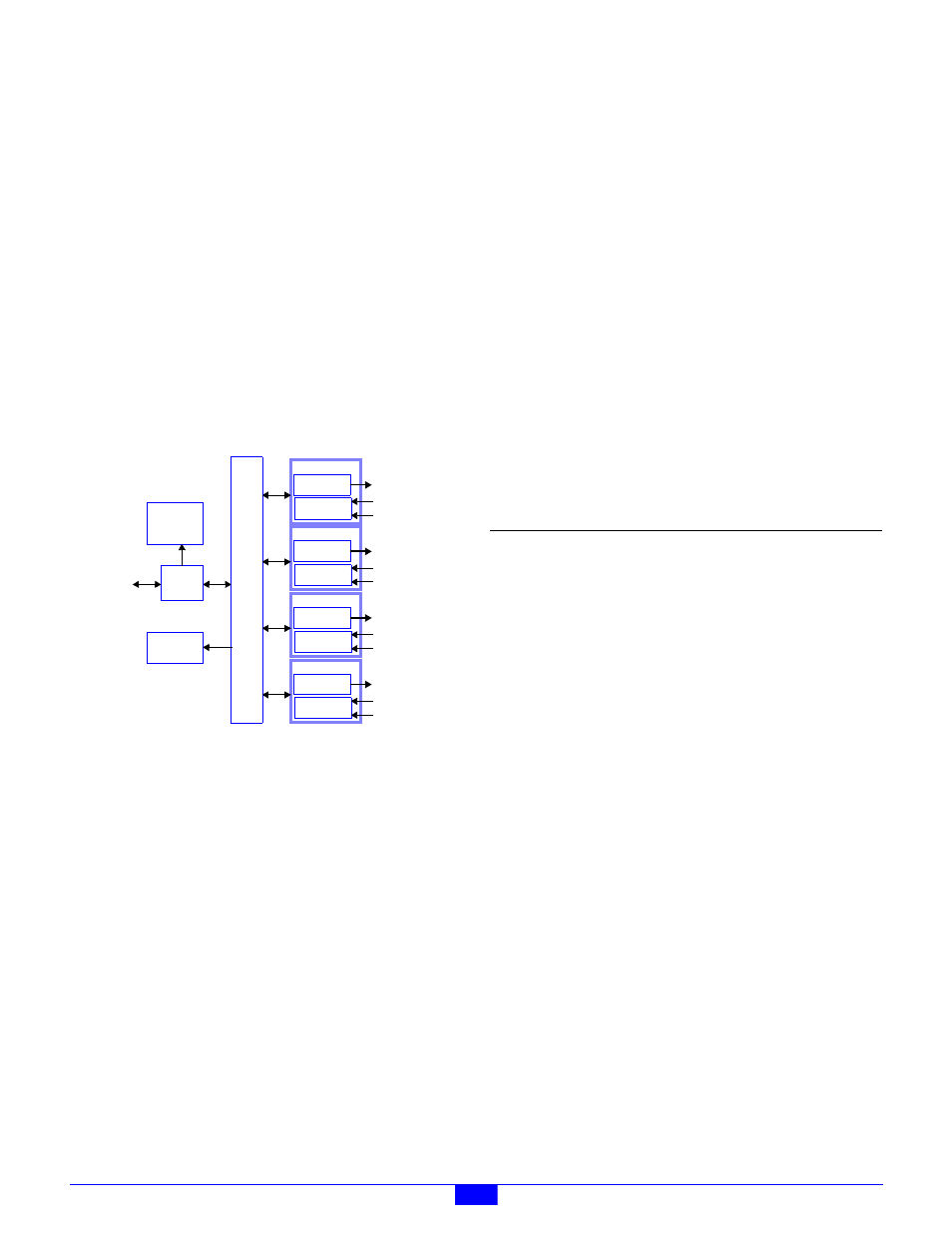
Model 2612 is a smart I/O module (IOM) that has four sensor
interface channels that are optimized for precision
measurement of passive resistive devices such as strain gauges,
RTDs and thermistors. The 2612 may be connected to any
IOM port on a model 2601 main module (MM) by means of a
single Cat-5 cable.
Each channel consists of an independent, fully differential
analog-to-digital converter (ADC) and a programmable
excitation generator. The ADC has inputs for both the
differential sensor signal and a differential reference voltage,
thus enabling the ADC to eliminate gain errors via ratiometric
conversion.
Figure 38: Model 2612 Block Diagram
Analog input subsystems include special circuitry that
implement fully electronic calibration. Excellent long-term
accuracy is achieved through the combination of high quality
on-board reference standards and the total absence of
mechanical trims.
The module’s electrical connectors are optimized for direct
connection to field wiring, in most cases eliminating the need
for external field wiring termination systems. All field wiring
is attached directly to the module by means of pluggable
connectors so that downtime will be minimized should it
become necessary to replace a module.
The entire module is automatically reset by a built-in watchdog
timer if an internal fault develops. Also, the module
automatically resets if the MM fails to communicate to it
within a programmable time interval.
Diagnostic LEDs include Power, Heartbeat, and
communication status. A self-test is performed automatically at
power-on and reset, and any detected fault conditions are
displayed on the status indicators.
A high-efficiency, on-board power supply produces all
required operating voltages from a single 24VDC source,
which is obtained from the MM via the module’s IOM port.
Test points are provided for all power supply voltages and
analog I/O signals.
8.2 Conversion Modes
Each channel is assigned a “conversion mode,” which specifies
its input conversion rate. This mode specifier has two parts:
the Oversample Ratio and Speed Multiplier.
8.2.1 Oversample Ratio
The oversample ratio (OSR) determines a number of
operational parameters as shown in Table 21.
Table 21: Behavior for various OSR settings
For example, with OSR=32768, the first null (notch) of the
digital filter occurs at approximately 55 Hz. This setting
provides better than 80dB rejection in the range from 49Hz to
61Hz.
Rejection of the first notch frequency and its multiples (up to
1.8MHz) exceeds 120dB. Effective noise bandwidth is a
measure of how the ADC will reject wideband input noise up
to the sample rate.
8.2.2 Speed Multiplier
The speed multiplier, which is used to double the input
conversion rate, may be enabled or disabled for each channel.
All other parameters (e.g., RMS Noise, Effective Bits) in Table
21 are unaffected by the speed multiplier. One additional cycle
of latency will be inserted between input signal and output data
when the speed multiplier is active.
µC
Input
IOM
Port
To 2601
IOM Port
Status
LEDs
Power
Supply
ADC
ADC
Power
Supply
Reference
Excitation
Chan0
Input
ADC
ADC
Power
Supply
Reference
Excitation
Chan1
Input
ADC
ADC
Power
Supply
Reference
Excitation
Chan2
Input
ADC
ADC
Power
Supply
Reference
Excitation
Chan3
OSR
RMS
Noise
Conversion
Rate (Hz)
First Notch
(Hz)
–3dB Point
(Hz)
Effective
Bits
64
23µV
3515.6
28125
1696
17
128
4.5µV
1757.8
14062.5
848
20.1
256
2.8µV
878.9
7031.3
424
20.8
512
2µV
439.5
3515.6
212
21.3
1024
1.4µV
219.7
1757.8
106
21.8
2048
1.1µV
109.9
878.9
53
22.1
4096
720nV
54.9
439.5
26.5
22.7
8192
530nV
27.5
219.7
13.2
23.2
16384 350nV
13.75
109.9
6.6
23.8
32768 280nV
6.875
54.9
3.3
24.1