6 specifications – Sensoray 2600 User Manual
Page 62
2600 Family Instruction Manual
57
Chapter 9 : Model 2620 Counter Module
time has been programmed so that the appropriate gate period
will be generated.
If the internal time gate generator can’t be used for some
reason (e.g., irregular gate time or different channels must
operate with different gate times) then a second counter
channel must be configured to serve as a gate generator for the
frequency counting channel.
The frequency counting channel is configured as a “gated pulse
counter.” It counts pulses from an external signal while the
counting gate is active. When a measurement is completed, the
result is latched and the next measurement begins
automatically. The most recently acquired measurement value
may be read from the latch at any time
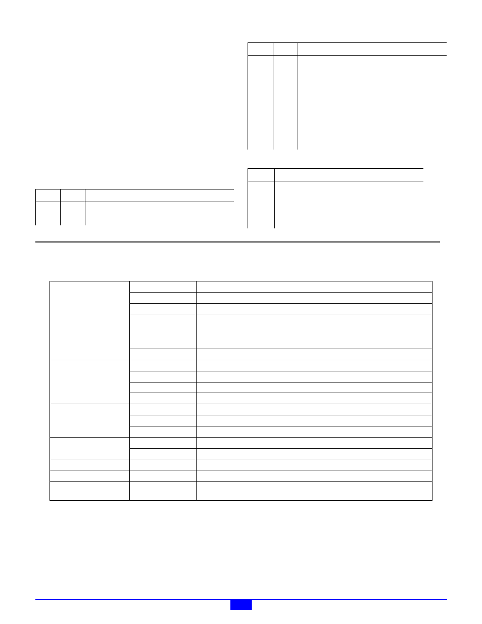
Set the Mode register as follows:
Connect the channel as follows:
9.6 Specifications
Field Value
Notes
OM
X
XP
0
Index (gate) polarity is active high.
PL
1
Preload on index (gate) leading edge.
LAT
1
Latch on index (gate) leading edge.
CET
1
Enable counting on index (gate) leading edge.
OP
X
M
4
Count external, single-phase clock.
CD
0
PLM
0
Use only Preload0, which must contain 0.
XC
1
Index connected to internal time gate generator.
Signal
Connect To
ClkA
Input signal to be measured.
ClkB
+5V or open (count up)
Index
NC
Output
NC
Field Value
Notes
Table 28: Model 2620 Specifications
Counters
Resolution
32 bits
Counter channels
4
Count rate
10 MHz, maximum.
Input clock
Maximums (derate for deviations from 50% duty cycle):
2.5 MHz @ quadrature x4.
5 MHz @ quadrature/mono x2.
10 MHZ @ quadrature/mono x1.
Internal clock
10 MHz.
Input/Output Signals
Clock input
RS-422 differential, TTL/5VCMOS compatible, ±7V CMV maximum.
Index input
RS-422 differential, TTL/5VCMOS compatible, ±7V CMV maximum..
Count Enable input
TTL/5VCMOS compatible.
Counter output
TTL/5VCMOS compatible.
Device Power Outputs
Output voltage
5VDC ±5%.
Output current
400mA, max., total for all channels.
Fuse
Socketed 500mA fuse per channel.
Mating Connectors
(*) = included with module
IOM port (qty 1)
RJ-45 plug, AMP 554169 or equivalent
Counter I/O (qty 4)
(*) Pluggable TB, 10-pin, RIA 31166110 or equivalent
Temperature
Operating range
0 to 70°C
Power
Input power
+24V ±5% @ 30mA, not including external device power.
Dimensions
Outer dimensions
5.0H x 4.1W x 2.0D inches, including DIN mounting frame. Depth is specified with respect
to surface of DIN rail support panel; additional clearance required for field wiring.