3 channel operating modes, 4 reset, 5 reserved connectors – Sensoray 2600 User Manual
Page 69: 1 output operation, 2 input operation, 3 output modes, 4 input debounce
2600 Family Instruction Manual
64
Chapter 11 : Model 2652 SSR Module
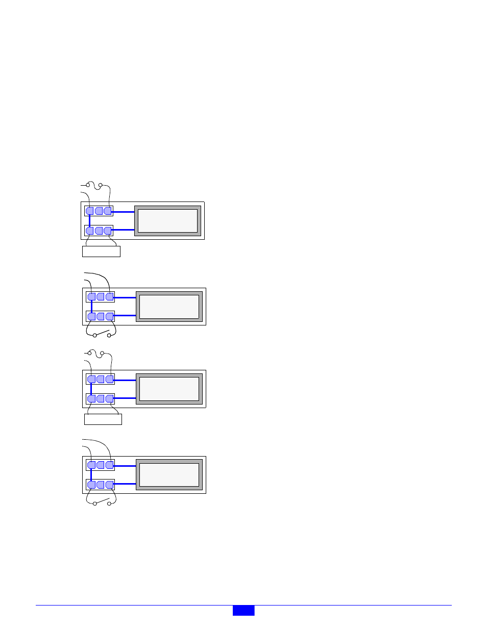
The Line- and Load- signals are connected together by circuit
board traces as indicated by the heavy blue lines in Figure 60.
For AC and DC output modules, the power supply should be
wired to the Line connector and the load device should be
wired to the Load connector. The Line+ and Load+ signals are
connected together by the SSR only when the SSR is
energized. It is recommended that the circuit be protected with
a fuse or circuit breaker on the Line side.
For AC and DC input modules, the line supply should be wired
to the Line connector and the contact should be wired to the
Load connector.
Figure 60: Field Wiring Diagrams
Sixteen mating connector shells (AMP part number 172166-1)
are supplied with the module for field wiring termination. Two
crimp pins (AMP part number 770988-1) are provided for each
shell. Each crimp pin must be attached to a field wire and then
inserted into its connector shell.
11.2.5 Reserved Connectors
Connectors JP9 and JP10 are reserved for manufacturing
programming and test. Application installations should leave
these unconnected.
11.3 Channel Operating Modes
Each channel may be independently operated as an input or
output, with AC or DC power and load by installing the
appropriate SSR type into the channel’s SSR socket.
11.3.1 Output Operation
When a channel is using an output SSR, the client simply
programs the channel’s output driver to the desired state.
11.3.2 Input Operation
When used with an input SSR, the client must ensure that it
never programs a channel’s output driver to its active state, as
this would override the SSR. Instead, the client must leave the
output driver in its default, inactive state and allow the SSR to
drive the channel’s physical state.
11.3.3 Output Modes
SSR channels support two different output modes: Standard
and PWM. In the Standard mode, a channel’s output driver is
directly controlled by the client as described in Section 11.3.1.
In the PWM mode, the channel’s output driver is cycled on and
off at a client-specified rate and duty cycle.
The output mode may be independently configured for each
channel. For example, channel 0 can operate in the PWM
mode while channels 1 to 7 operate in the Standard output
mode.
11.3.4 Input Debounce
All SSR channel physical states are sampled every 10
milliseconds. The on-board microcontroller applies a
debounce filter to the sampled states, resulting in a 10
millisecond debounce period.
When acquiring physical channel states from the 2652 module,
the client always receives the debounced image of the physical
states, which is delayed 10 milliseconds by the debounce
function.
11.4 Reset
Upon module reset, all channels default to the Standard
operating mode and all SSR output drivers default to the
inactive state. A 2652 module will experience a module reset
in response to any of the following conditions:
• Module power-up.
• Watchdog time-out due to soft or hard fault.
• SoftReset or HardReset action request from the client.
H
N
Load
AC Output SSR
AC
Supply
H
AC
N
AC Input SSR
Supply
H
AC
N
AC Input SSR
Supply
Load
DC Output SSR
+
-
DC
Supply
DC Input SSR
+
-
DC
Supply