1 introduction, 2 hardware configuration, 1 diagnostic leds – Sensoray 2600 User Manual
Page 55
2600 Family Instruction Manual
50
Chapter 9 : Model 2620 Counter Module
Chapter 9: Model 2620 Counter Module
9.1 Introduction
The model 2620 is a smart I/O module (IOM) that has four
identical 32-bit programmable counter channels, numbered 0
to 3.
By means of a single Cat-5 cable, the 2620 may be connected
to any IOM port on a model 2601 main module (MM). The
onboard microcontroller communicates with the MM by means
of an optically isolated, asynchronous serial interface.
Counter channels are designed to support these applications:
• Incremental encoder interface, with quadrature decoder
and clock multiplier (x1, x2 and x4).
• Pulse generator, with software, hardware or periodic
interval triggering.
• PWM generator.
• Pulse width measurement.
• Period measurement.
• Frequency measurement.
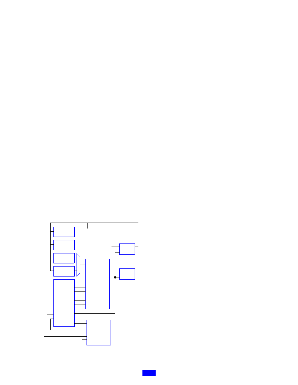
As shown in Figure 44, each channel has two clock inputs (“A”
and “B”), one index input, one output, and a fused 5 Volt DC
output for supplying operating power to an incremental
encoder or other low-power device. The channel infrastructure
consists of a 32-bit counter core, two 32-bit preload registers,
32-bit latch register, mode register and control register.
Figure 44: Counter Channel Block Diagram
Each channel is independently programmable for clock type
(quadrature x4/x2/x1 or single phase) and index function. The
index input can be programmed to behave in various ways,
including setting the counter core to a specific value and/or
latching counts upon index edge events.
The maximum count rate for each counter channel is 10 MHz.
Single-phase clock sources having a 50 percent duty cycle can
be counted at this rate. For other duty cycles, the maximum
count rated must be derated based on the clock’s pulse width.
Quadrature clocks up to 2.5 MHz are supported, derated for
non-symmetrical phasing or deviations from 50 percent duty
cycles.
A free-running 16-bit counter serves as a shared time stamp
generator for all channels. The time stamp resolution, which is
common to all channels, may be programmed to 1, 10, 100 or
1000 microseconds. Each channel synchronously latches the
time stamp counts whenever its counter core is transferred to
its output data latch.
The free-running counter also generates pulses that may be
used as gate generators in frequency counting applications. A
clock divisor, which is common to all channels, may be
programmed to to set the pulse width to any value from one to
16,382 milliseconds, in one-millisecond increments.
All clock and index inputs employ fully differential RS-422
line receivers for superior noise immunity. The line receivers
include termination resistors for enhanced noise rejection in
noisy environments. Although clock and index inputs are
optimized for RS-422 differential pairs, they are also TTL and
5V CMOS compatible.
9.1.1 Diagnostic LEDs
• LNK - Lights when the 2620 has established a
communication link with the 2601 main module.
• HBT - “Heartbeat” indicator flashes to show that the
on-board CPU is healthy.
• ACT - Lights briefly when an Ethernet client command is
executed.
• RST - Lights briefly when the module is reset.
• Channel Activity LEDs - These four LEDs indicate the
presence of a dynamic signal at the counter core’s clock
input. Each channel has one activity LED, located near to
its terminal block. Each LED flashes at a constant rate
while the associated core’s clock signal is changing.
9.2 Hardware Configuration
The 2620 module is configured by connecting cables and
devices as described in this section.
Counter Core
LOAD
ENABLE
RESET
ClkA
ClkB
UP/DOWN
D<31:0>
Preload0
Register
Preload1
Register
Internal
Data Bus
Control
Logic
Index
Q<31:0>
Control
Register
Mode
Register
CLOCK
Latch
Output
Field
+5V
COM
Wiring
Connector
Latch
Time Stamp
Generator
Gate
Generator