Chapter 2: system wiring, 1 overview, 2 mm connectors – Sensoray 2600 User Manual
Page 9: 1 terminal block, 2 power daisy-chain, 3 ethernet connector
2600 Family Instruction Manual
4
Chapter 2 : System Wiring
Chapter 2: System Wiring
2.1 Overview
This chapter discusses the electrical connectors on the MM and
how to interconnect the MM, IOMs and power supplies to
form a complete system.
2.2 MM Connectors
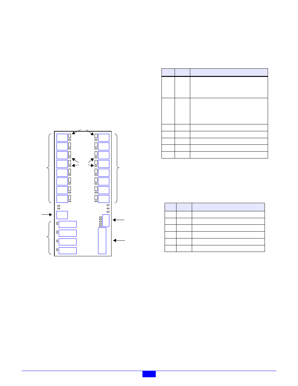
The locations of all of the connectors on the MM are shown in
Figure 5. Each of the connectors is discussed in detail in the
following sections.
Figure 5: MM Connector Locations
2.2.1 Terminal Block
The MM employs a pluggable terminal block (TB) to connect
one or more power supplies to the module system. The TB is
installed onto Header J22.
At least one 24VDC power supply must be connected to the
TB to render the module system functional. This power source
supplies operating power to the MM and to all IOMs that are
connected to the MM’s IOM ports.
In addition to the required 24VDC supply, as many as five
auxiliary DC power supplies may be connected to the TB on
circuits PWR0 to PWR4 (see Table 2). These circuits may be
used to supply power to any IOMs that require external power
supplies for I/O operation, such as the Model 2610 digital I/O
module and the Model 2650 relay module. Power supplies
connected to these circuits may be routed through interlock
contacts, and they may have output amplitudes less than 24V.
2.2.2 Power Daisy-Chain
Connector P1 may be used to daisy-chain the +24V and PWR0
to PWR4 power supply voltages out to any IOMs that require
access to these voltages.
Five LED indicators are located adjacent to P1. Each of these
indicators lights when power is applied to its associated PWR
input signal, as shown on the silkscreen legend next to each
indicator.
2.2.3 Ethernet Connector
An RJ-45 jack at J21 is used for interfacing the MM to a
10BaseT/100BaseTX Ethernet network. A standard
Category-5 shielded or unshielded twisted pair (STP or UTP)
patch cable should be plugged into this jack, and the other end
of the patch cable should be plugged into an Ethernet switch.
If the MM will be connected directly to a dedicated Ethernet
client, a Category-5 UTP crossover cable should be used
instead.
Two LED indicators, located near to J21, light to indicate link
detection and receive activity.
IOM9
IOM8
IOM10
IOM11
IOM12
IOM12
IOM12
IOM12
IOM1
IOM0
IOM3
IOM2
IOM5
IOM4
IOM7
IOM6
COM4
COM3
COM2
COM1
Ethernet
J21
J22
P1
Power
Input
Power
Daisy-
Chain
Output
Serial
Comm.
Ports
Fuses
IOM
Ports
IOM
Ports
Link
LEDs
Table 2: Pinout of Pluggable Terminal Block at J22
Pin
Name
Function
1, 2
+24V
+24VDC power for the MM and all connected
IOMs. One of these pins must be connected to
the +24V supply; connections to the other +24V
pin may be used to minimize external TBs.
3, 4, 5
GND
Return for the +24VDC power supply that is
connected to pins 1 and 2. One of these must be
connected to the 24VDC power supply return;
connections to the other GND pins may be used
to minimize external TBs.
6
PWR0
Optional positive DC power #0.
7
PWR1
Optional positive DC power #1.
8
PWR2
Optional positive DC power #2.
9
PWR3
Optional positive DC power #3.
10
PWR4
Optional positive DC power #4.
Table 3: Pinout of Connector P1
Pin Name
Function
1
+24V
+24V power, always on.
2
0
Optional positive DC power #0.
3
1
Optional positive DC power #1.
4
2
Optional positive DC power #2.
5
3
Optional positive DC power #3.
6
4
Optional positive DC power #4.