3 excitation, 4 analog inputs, 5 hardware configuration – Sensoray 2600 User Manual
Page 49: 1 self-heating errors, 1 reference voltage range, 2 input voltage range, 1 bridge completion shunt
2600 Family Instruction Manual
44
Chapter 8 : Model 2612 Strain Gauge/RTD Module
8.3 Excitation
Each channel has a dedicated, programmable power supply
which may be used to to provide excitation for a passive sensor
such as a strain gauge, RTD or thermistor. Under software
control, the power supply may be programmed to output one of
four constant voltages: 1.25V, 2V, 3V or 5V. See section
Section 8.7.3 for programming details.
The excitation supplies are designed to power isolated resistive
devices, so you should not connect the excitation outputs to
external power supplies as this is likely to damage the
module’s circuitry.
To ensure good voltage regulation by the excitation supply, it
is necessary to draw the minimum output current as specified
in Section 8.8. This minimum current can be drawn entirely
through the serial sensor/resistor comination, or an additional
shunt resistance may be placed across the supply for this
purpose.
In the case of RTDs, thermistors and other single-element
devices, an external fixed resistor must be supplied to form a
voltage divider so that the device will produce a voltage that is
a function of its resistance.
8.3.1 Self-Heating Errors
In the process of measuring a passive resistive device, an
electric current must flow through the device to produce a
measurable voltage. Since the device has electrical resistance,
this current results in power consumption within the device
that will tend to raise its temperature (i.e., “self-heating”).
In the case of temperature sensors such as RTDs and
thermistors, self-heating can cause a measurement error
because the sensor resistance may not accurately reflect the
ambient temperature.
Self-heating can be minimized by minimizing the current
through the sensor and/or attaching the sensor to a heat sink.
Sensor current can be minimized by connecting a large
resistance in series with the sensor. Chose the largest possible
series resistance that will give the required measurement
resolution. Keep in mind that an additional shunt resistor may
be required across the excitation supply to ensure that its
minimum required load current is satisfied.
8.4 Analog Inputs
Each channel incorporates a dedicated ADC to convert a
differential sensor voltage to a digital value. Analog input
channels utilize fully differential signal paths to help maintain
measurement accuracy in electrically noisy environments. In
addition, each analog input channel is provided with a pair of
reference inputs; this pair comprises a differential reference
that sets the input range for the channel.
The ADC produces a value that is proportional to the
difference voltage between the channel’s differential input
pair, within the input range defined by the reference inputs.
The digitized value is the ratio of the differential input voltage
to the reference voltage.
8.4.1 Reference Voltage Range
The reference voltage is a differential voltage that is applied to
the Ref+ and Ref- inputs. This differential voltage (Ref+
minus Ref-) must fall within the range from 0V to +5V.
The Ref+ and Ref- absolute input voltage must be within the
range from 0V to +5V with respect to Power-.
8.4.2 Input Voltage Range
The differential input voltage applied to Input+ and Input-
must not exceed half of the reference voltage. For example,
with Ref+ set to 5V and Ref- set to 0V, the differential input
voltage must be in the range from -2.5V (full scale negative) to
+2.5V (full scale positive). Outside this range, the converter
indicates an overrange or underrange condition.
To prevent circuit damage, the voltage on all input pins (with
respect to the
Power-
pin) must fall within the voltage range
0V to +5V.
8.5 Hardware Configuration
Each input channel is provided with a 6-pin header (called the
input programming block, or IPB) that is designed to accept
hardware programming shunts. Various configuration options
are programmed by installing shunts in the appropriate
positions on the IPB, as described in the following sections.
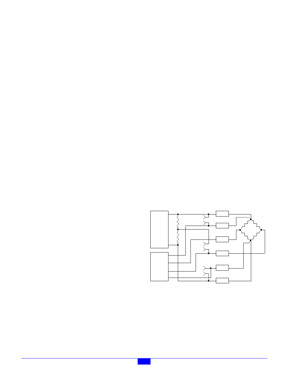
Figure 39: Default Configuration: All Shunts Removed
Full-bridge strain gauges may be connected as shown in Figure
39 to implement a 6-wire interface with remote excitation
sensing.
8.5.1 Bridge Completion Shunt
Each channel has a 2:1 (2.5+2.5 KOhm, 0.1%) divider
connected across the negative and positive power outputs.
This divider serves as bridge completion resistors for
half-bridge strain gauges.
Power+
Ref+
Input+
Input-
Ref-
Power-
P
o
w
e
r
A
D
C
1
2
3
4
6
5