3 relay power selection shunt, 4 i/o connectors, 5 reserved connectors – Sensoray 2600 User Manual
Page 64
2600 Family Instruction Manual
59
Chapter 10 : Model 2650 Relay Module
select relay channels in the event of a critical condition such as
emergency stop (ESTOP) activation, open safety hood, etc.
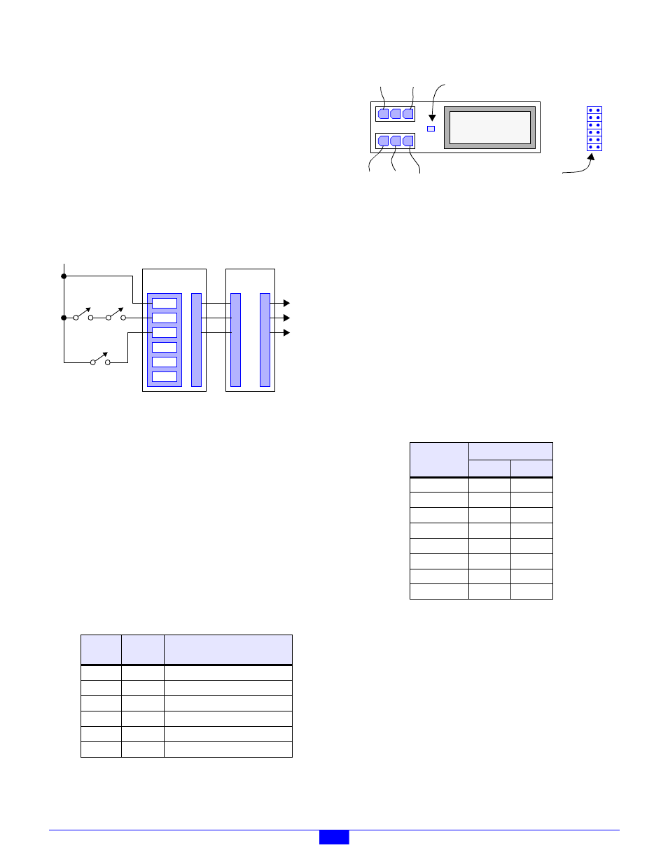
Figure 35 illustrates a system in which PWR0 is connected to
multiple system emergency stop contacts, and PWR1 is routed
through a safety hood interlock contact. Note that all of the
external power sources are daisy-chained from module to
module. Any relay that is configured to use PWR0 will
de-energize when either ESTOP contact is opened, and any
relay that is configured to use PWR1 will de-energize when the
hood opens. All other relays use the +24V “always on” power
source and thus are unaffected by interlock contacts. PWR2,
PWR3 and PWR4 are not used in this application.
Figure 53: Wiring Example with Interlock Contacts
Use Sensoray cable assembly, part number 2600C1, to connect
P17 or P18 to the power daisy chain.
10.2.3 Relay Power Selection Shunt
Each relay channel may be independently operated from any of
the six external power sources (that are connected to P17 and
P18) by installing the appropriate programming shunt on the
module.
A shunt receptacle matrix is provided for each channel. Each
matrix has six shunt positions, corresponding to the six
external power sources. As shown in Table 17, a 2mm
programming shunt (supplied with the 2650) must be installed
at the position corresponding to the relay channel’s target
power source. Only one shunt should be installed per matrix.
Each channel’s shunt receptacle matrix is located adjacent to
its relay socket as shown in Figure 54.
Figure 54: Relay Channel Layout (top view)
10.2.4 I/O Connectors
The 2650 module employs sixteen connectors for interfacing
relay line and load power signals. Each relay channel uses two
of these connectors, one for line and one for load, as shown in
Table 30.
For AC power switching, the hot and neutral line-side signals
connect to the top connector (see Figure 54) at the terminals
shown as Hot and Neut. The AC load is typically connected to
the bottom connector across the COM and NO (normally open)
terminals, and thus hot power is switched onto the NO terminal
only when the relay is energized. Terminals Neut and COM
are connected together by circuit board traces.
Both AC and DC loads may be controlled. Please refer to the
RH1B relay data sheet for detailed specifications.
Sixteen mating connector shells (AMP part number 172166-1)
are supplied with the module for line and load field wiring
termination. Three crimp pins (AMP part number 770988-1)
are provided for each shell. Each crimp pin must be crimped
onto a field wire and then inserted into its connector shell.
10.2.5 Reserved Connectors
Connectors JP1 and JP10 are reserved for manufacturing
programming and test. Application installations should leave
these unconnected.
Table 29: Interlock Power Programming Matrix
PWB
Label
Shunt
Pins
Selected Power Source
+24V
1-2
+24V power, always on (default)
0
3-4
Optional positive DC power #0.
1
5-6
Optional positive DC power #1.
2
7-8
Optional positive DC power #2.
3
9-10
Optional positive DC power #3.
4
11-12
Optional positive DC power #4.
PWR4
PWR3
PWR2
PWR1
PWR0
+24V
2601 MM
TBLK
@J22
P1
P17
P18
2650 RLY
To
Other
IOMs
+24V
ESTOP
SW1
ESTOP
SW2
HOOD
INTERLOCK
Table 30: Line and Load Connectors
Relay
Channel
Connector
Line
Load
CH0
P15
P16
CH1
P13
P14
CH2
P11
P12
CH3
P9
P10
CH4
P7
P8
CH5
P5
P6
CH6
P3
P4
CH7
P1
P2
Relay
12
10
8
6
4
2
11
9
7
5
3
1
+24V-
PWR0-
PWR1-
PWR2-
PWR3-
PWR4-
Indicator lights when relay is energized
Hot
Line
Load
Neut
COM
NC
NO
Power Programming Matrix
(Neut) (Hot) (Hot)