1 introduction, 2 hardware configuration, 1 iom network connector – Sensoray 2600 User Manual
Page 74: 2 interlock power connectors
2600 Family Instruction Manual
69
Chapter 12 : Model 2653 SSR Module
Chapter 12: Model 2653 SSR Module
12.1 Introduction
Model 2653 is a smart I/O module (IOM) that monitors and
controls up to sixteen solid state relays (SSRs). All SSRs are
socketed so that SSR types may be mixed or left unpopulated,
as required. Each SSR socket may be populated with any
supported SSR type, including AC in, AC out, DC in and DC
out. SSRs are secured to the IOM via integral hold-down
screws that are retained by pem nuts on the IOM.
The module’s microcontroller, which provides I/O services to a
remote client, communicates with the client by means of a
standard Category-5 UTP cable over an optically isolated,
asynchronous serial interface.
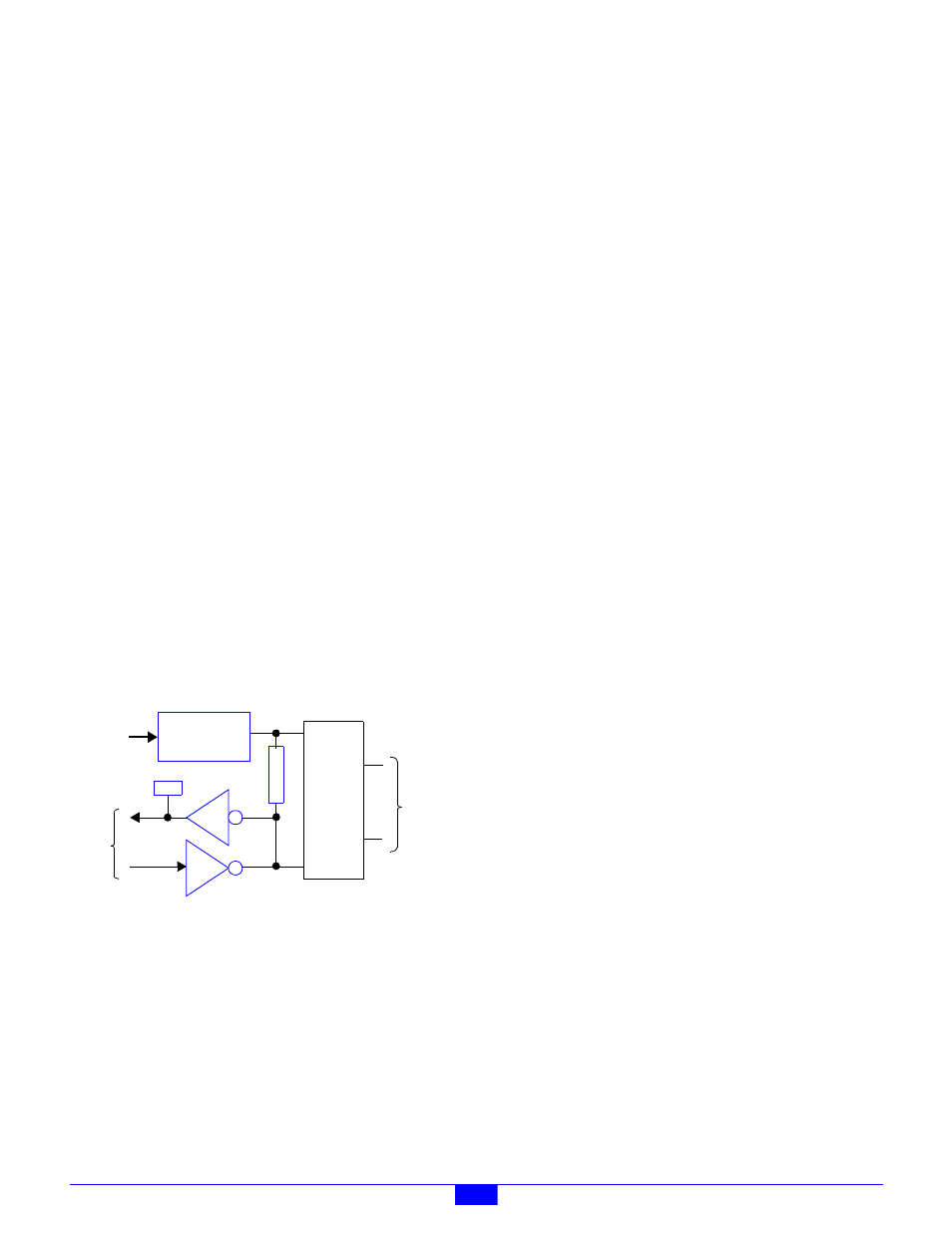
As shown in Figure 62, each relay channel includes:
• Standard SSR socket.
• Active-low, open-collector driver for output SSR types.
• Channel monitor circuit, to enable the client to acquire the
channel’s physical state.
• Indicator LED that lights when the channel is energized by
either the output driver or by an externally generated
signal arriving from an input SSR.
• Two finger-safe field I/O connectors per channel.
• Shunt programming matrix for implementing interlocked
fail-safe operation.
Figure 62: SSR Channel Block Diagram
The client can program and read back the state of each
channel’s output driver, and it can acquire the debounced state
of each channel’s physical signal. The microcontroller
debounces all acquired channel states with a 10 millisecond
software debounce filter. When used in conjunction with
output SSR types, all channels have the ability to
autonomously produce PWM type output signals at a rate and
duty cycle specified by the client.
Each SSR channel includes an LED indicator that lights when
the channel is active. The indicator lights regardless of
whether the channel is driven by an external signal source
(through an input SSR type) or by the channel’s output driver.
On-board, finger-safe connectors enable direct connection to
field wiring without the need for intermediate terminal
blocks. One connector is used for the line connection and the
other for load.
Integral support is provided for system interlock circuits and
multiple power supply voltages. Each SSR channel may be
independently powered from any of up to six external DC
power sources.
The communication interface between the client and the
on-board microcontroller is optically isolated to ensure
error-free operation in demanding industrial environments.
12.2 Hardware Configuration
The 2653 module is configured by installing programming
shunts and connecting various cables to the module as
described in this section.
12.2.1 IOM Network Connector
A single RJ-45 connector, J1, is used to connect the 2653
module to its client. This should be mated to a standard UTP
(unshielded twisted pair) Category-5 cable.
The other end of this cable will be connected to one of the
sixteen IOM ports on a model 2601 module.
12.2.2 Interlock Power Connectors
The monitoring and control circuitry on each SSR channel is
powered from an external DC power source. At least one
external power source is required to make the SSR channels
functional. Up to six independent DC power sources are
supported. Note that an SSR’s control voltage must match its
selected DC power supply voltage. For example, use an SSR
such as the 70-OAC24 (24VDC control, 120VAC output) for
AC output applications that will be operating from a 24VDC
supply.
Connectors P33 and P34 convey power to the SSR monitoring
and control circuitry from external DC power sources. All
external power sources must supply positive DC voltages with
respect to system ground. The current return of each external
power source must connect to the system ground.
As shown in Figure 63, connectors P33 and P34 are identical in
function and pinout. The external DC power sources may be
connected to either P33 or P34. If other IOMs require access
to these external power sources, the unused connector may be
used to daisy-chain power out to other IOMs. In this manner,
power can be distributed to any arbitrary number of external
IOMs without the use of dedicated power distribution terminal
blocks.
P
u
l
l
-
u
p
Shunt
Programming
Matrix
To
External
Power
Field
I/O
LED
open
col.
µC
PWR
I/O
SSR