3 pwm generator, 4 pulse width measurement, 5 period measurement – Sensoray 2600 User Manual
Page 61: 6 frequency measurement
2600 Family Instruction Manual
56
Chapter 9 : Model 2620 Counter Module
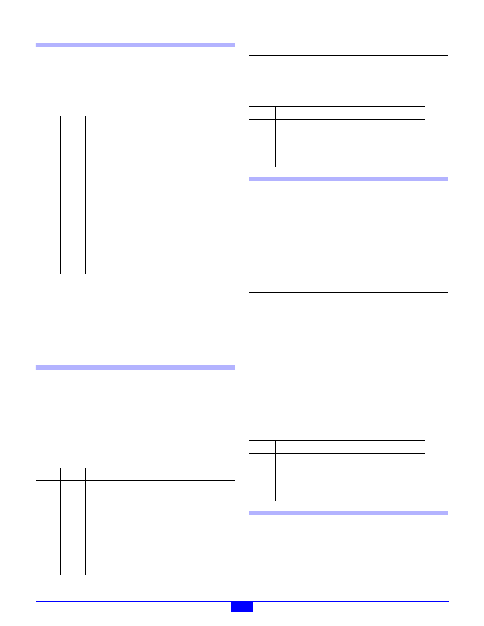
9.5.3 PWM Generator
This configures a counter channel so that it will toggle its
output signal at periodic intervals, with programmable period
and duty cycle.
Set the Mode register as follows:
Connect the channel as follows:
9.5.4 Pulse Width Measurement
This configures a counter channel so that it will measure the
width of pulses applied to the index input. When a
measurement is completed, the result is latched and the next
measurement begins automatically. The most recently
acquired measurement value may be read from the latch at any
time.
Set the Mode register as follows:
Connect the channel as follows:
9.5.5 Period Measurement
This configures a counter channel so that it will measure the
period of a squarewave applied to the index input. When a
measurement is completed, the result is latched and the next
measurement begins automatically. The most recently
acquired measurement value may be read from the latch at any
time.
Set the Mode register as follows:
Connect the channel as follows:
9.5.6 Frequency Measurement
This configures a counter channel so that it will measure the
frequency of a periodic signal. In this example, the count gate
is generated by the internal time gate generator, which is
common to all counter channels. It is assumed that the gate
Field Value
Notes
OM
1
Toggle output when core transitions to zero
counts.
XP
X
PL
2
Preload on zero counts reached.
LAT
0
Latch on soft trigger.
CET
0
OP
*
Set output polarity as required.
M
7
Use internal clock.
CD
0
PLM
1
Use both preload registers. Preload0/Preload1
must be programmed with the on/off output times,
respectively, for the desired period and duty cycle.
XC
0
External index signal.
Signal
Connect To
ClkA
NC
ClkB
GND (count down)
Index
NC
Output
PWM output signal.
Field Value
Notes
OM
X
XP
0
PL
1
LAT
1
Latch on index leading edge.
CET
1
Start counting on index leading edge.
OP
X
M
7
Use internal clock.
CD
1
Stop counting on index trailing edge.
PLM
0
Use only the Preload0 register. Preload0 must be
programmed to zero.
XC
0
External index signal.
Signal
Connect To
ClkA
NC
ClkB
+5V or open (count up)
Index
Pulse input signal to be measured.
Output
NC
Field Value
Notes
OM
X
XP
*
Doesn’t matter, unless one signal edge has more
jitter than the other edge.
PL
1
Preload on index leading edge.
LAT
1
Latch on index leading edge.
CET
1
Enable on first index leading edge.
OP
X
M
7
Use internal clock.
CD
0
PLM
0
Use one preload register, which must contain 0.
XC
0
External index signal.
Signal
Connect To
ClkA
NC
ClkB
+5V or open (count up)
Index
Periodic input signal to be measured.
Output
NC
Field Value
Notes