Overtemp settings/info, Stuck relay settings/info, Overcurrent settings/info – Magnum Energy ME-RC Remote User Manual
Page 57: 0 operation
©2013 Magnum Energy, Inc.
50
5.0 Operation
• Overtemp
– The inverter/charger has shut down because the internal
power components (FETs and/or Transformer) have exceeded their safe
temperature operating range. When the unit has cooled down, it will
automatically restart and continue operation.
Remedy: If the fault occurs while inverting, reduce the load on the
inverter. If it occurs while charging, turn down the charge rate. If
this fault happens often, ensure the inverter is not in a hot area,
has proper ventilation, and the cooling fans inside the inverter are
working.
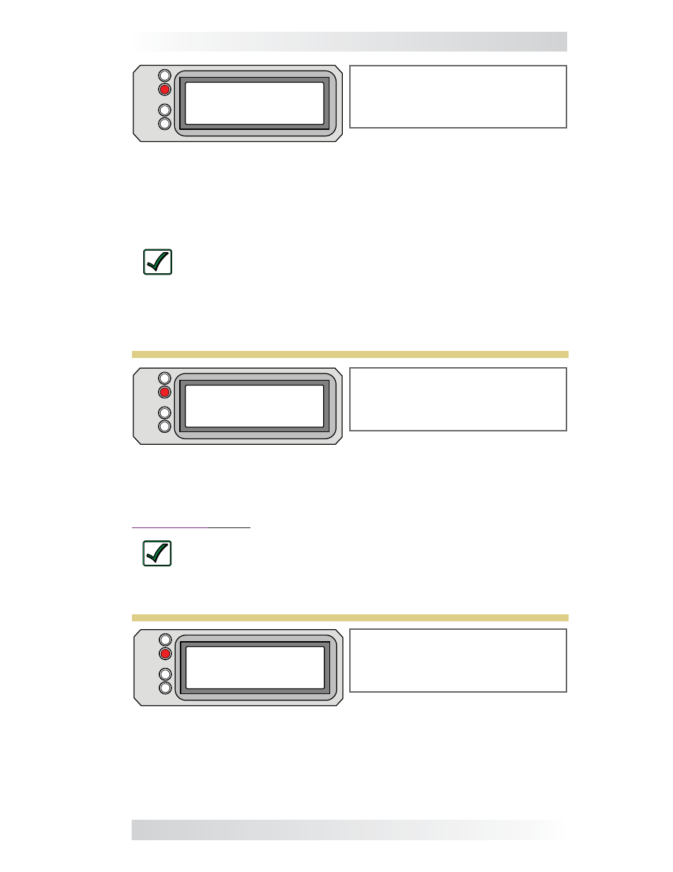
Overtemp appears on the LCD.
The FAULT (red) LED is on. The
PWR (green), CHG (green), and INV
(green) LEDs are off.
FAULT
PWR
CHG
INV
Overtemp
Settings/Info..
Figure 5-28, Overtemp Fault
Stuck Relay appears on the LCD.
The FAULT (red) LED is on. The
PWR (green), CHG (green), and INV
(green) LEDs are off.
FAULT
PWR
CHG
INV
Stuck Relay
Settings/Info..
Figure 5-29, Stuck Relay Fault
• Stuck
Relay
– This fault message displays when the inverter is
“inverting”, but the internal AC pass-thru relay that should be open while
inverting, is closed.
• Overcurrent – This fault shuts down the inverter to protect internal
power components. It may be caused by an excessive AC load. If the overload
condition lasts for less than 10 seconds, the unit will automatically restart
and resume operation. However, if the overcurrent condition occurs for more
than 10 seconds, the unit will shut down and will require a manual restart.
Remedy: This fault usually occurs because the connected AC loads
are larger than the inverter’s output capacity, there is a wiring short
on the AC output, or the wires are incorrectly installed. Once the
AC loads are reduced or the output wiring is corrected, manually
restart the inverter to resume operation. If this fault condition con-
tinues after all these recommendations, perform a inverter reset
(see Section 6.2).
Overcurrent appears on the LCD
and the FAULT (red) LED is on. The
PWR (green), CHG (green) and INV
(green) LEDs are off.
FAULT
PWR
CHG
INV
Overcurrent
Settings/Info..
Figure 5-27, Overcurrent Fault