Distances, Bus segments, Installation guidelines – BECKHOFF BC3150 User Manual
Page 26: Checking the profibus wiring
Safety Instructions
24
Fieldbus Components
Note
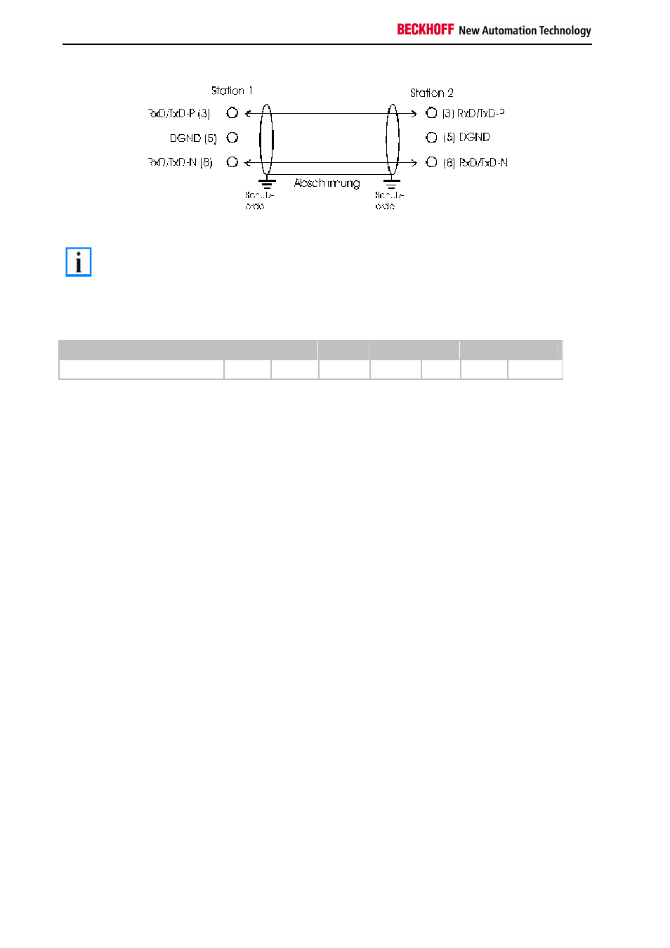
In systems with more than two stations all devices are wired in parallel. It is essential that
the bus cables are terminated with resistors at the conductor ends in order to avoid
reflections and associated transmission problems.
Distances
The bus cable is specified in EN 50170. This yields the following lengths for a bus segment.
Baud rate in kbits/sec
9.6
19.2
93.75
187.5
500
1500
12000
Cable length in m
1200
1200
1200
1000
400
200
100
Stubs up to 1500 kbaud <6.6 m; at 12 Mbaud stub segments should not be used.
Bus segments
A bus segment consists of at most 32 devices. 126 devices are permitted in a Profibus network. Repeaters are
required to refresh the signal in order to achieve this number. Each repeater is counted as one device.
IP-Link is the subsidiary bus system for Fieldbus Boxes, whose topology is a ring structure. There is an IP master in
the coupler modules (IP230x-Bxxx or IP230x-Cxxx) to which up to 120 extension modules (IExxxx) may be
connected. The distance between two modules may not exceed 5 m. When planning and installing the modules,
remember that because of the ring structure the IP-Link master must be connected again to the last module.
Installation guidelines
When assembling the modules and laying the cables, observe the technical guidelines provided by the Profibus User
Organization (Profibus Nutzerorganisation e.V.) for Profibus DP/FMS (see www.profibus.com).
Checking the Profibus wiring
A Profibus cable (or a cable segment when using repeaters) can be checked with a few simple resistance
measurements. The cable should meanwhile be removed from all stations:
1. Resistance between A and B at the start of the lead: approx. 110 Ohm
2. Resistance between A and B at the end of the lead: approx. 110 Ohm
3. Resistance between A at the start and A at the end of the lead: approx. 0 Ohm
4. Resistance between B at the start and B at the end of the lead: approx. 0 Ohm
5. Resistance between screen at the start and screen at the end of the lead: approx. 0 Ohm
If these measurements are successful, the cable is okay. If, in spite of this, bus malfunctions still occur, this is usually
a result of EMC interference. Observe the installation notes from the Profibus User Organization (www.profibus.com).