Diagnostic leds, Leds for power supply diagnosis, Leds for k-bus diagnostics – BECKHOFF BC3150 User Manual
Page 96: K-bus error code diagnostics
Safety Instructions
94
Fieldbus Components
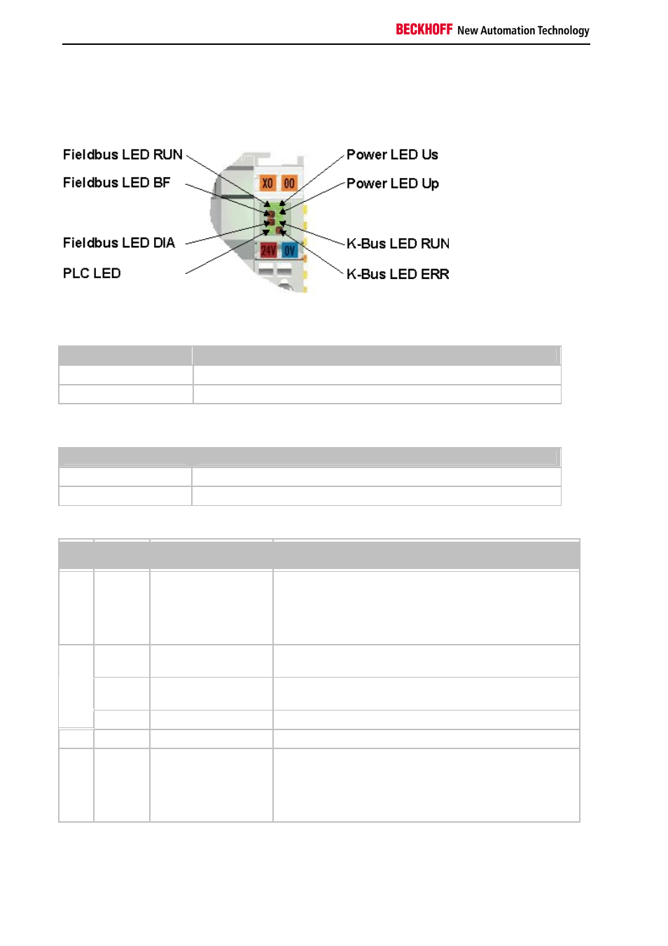
Diagnostic LEDs
The Bus Coupler features status indicator LEDs. The row of LEDs on the left describes the status of the fieldbus and
of the PLC. The row of LEDs on the right indicates the supply voltage and the K-Bus state.
LEDs for power supply diagnosis
LED (Power LEDs)
Meaning
LED Us
LED off: Bus Coupler has no voltage 24 V
DC
LED Up
LED off: No 24V
DC
power connected to the power contacts
LEDs for K-Bus diagnostics
LED (Power LEDs)
Meaning
LED RUN
LED off: no K-Bus update, LED on, flashing: K-Bus running
LED ERR
LED off: no error, LED flashing: see K-Bus error code
K-Bus error code diagnostics
Error
code
Error
argument Description
Remedy
0
-
EMC problems
•
Check power supply for overvoltage or undervoltage
peaks
•
Implement EMC measures
•
If a K-Bus error is present, it can be localized by a restart
of the coupler (by switching it off and then on again)
0
EEPROM checksum
error
Set factory settings with the KS2000 configuration software
1
Code buffer overflow
Insert fewer Bus Terminals. The programmed configuration has
too many entries in the table
1
2
Unknown data type
Software update required for the Bus Coupler
2
-
Reserve
-
3
0
K-Bus command error
•
No Bus Terminal inserted
•
One of the Bus Terminals is defective; halve the number
of Bus Terminals attached and check whether the error
is still present with the remaining Bus Terminals. Repeat
until the defective Bus Terminal is located.