External modem connectors, Data i/o interface (j8), 3 external modem connectors – Comtech EF Data SNM-1001 User Manual
Page 25: 1 data i/o interface (j8)
Installation
SNM-1001 Network Control Modem
2–4
Rev. 1
2.3
External Modem Connectors
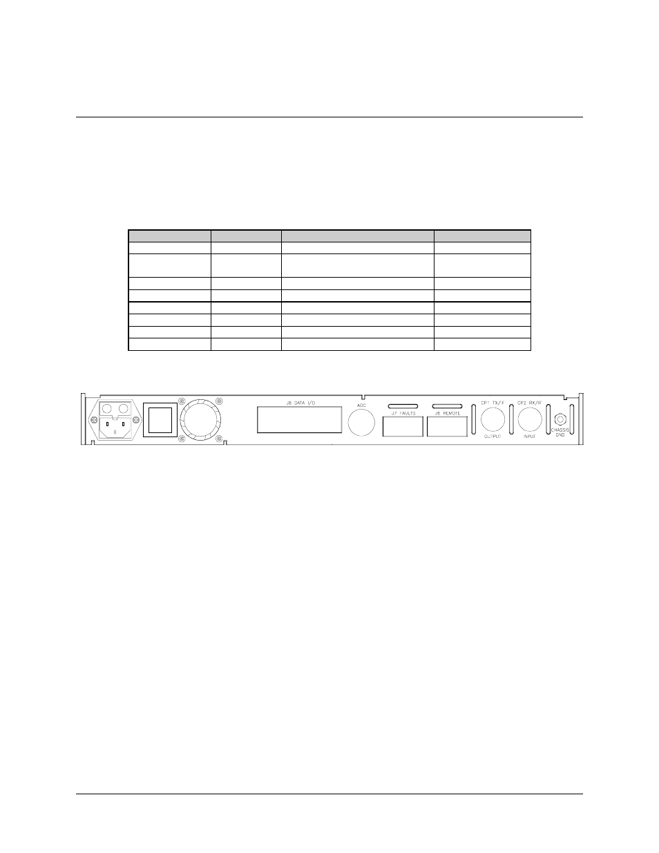
Connections between the modem and other equipment are made through five connectors.
These connectors are listed in Table 2-1 and their locations are shown in Figure 2-3. The
use of each connector is described in the following paragraphs.
Table 2-1. Rear Panel Connectors
Name
Ref. Design
Function
Connector Type
AC POWER
None
AC Power Input
Standard
DATA I/O
J8
DATA Input/Output (I/O)
EIA-422/449
Various
37-pin D
AGC
None
AGC Test Point
Test Point
FAULTS
J7
FORM-C Fault Relay Contacts
9-pin Female D
REMOTE
J6
Remote Interface
9-pin Female D
TX IF OUTPUT
CP1
TX IF Output
BNC
RX IF INPUT
CP2
RX IF Input
BNC
CHASSIS GND
None
Chassis Ground
#10-32 Stud
Figure 2-3. SNM-1001 Rear Panel View
2.3.1
DATA I/O Interface (J8)
The DATA I/O interface connector is used to interface data input and output signals to
and from the modem. J8 connects to the customer terrestrial equipment directly, or
through a protection switch. The modem operates with a single interface configuration.
The DATA I/O interface is EIA-422/449.