Comtech EF Data SNM-1001 User Manual
Page 26
SNM-1001 Network Control Modem
Installation
Rev. 1
2–5
2.3.1.1
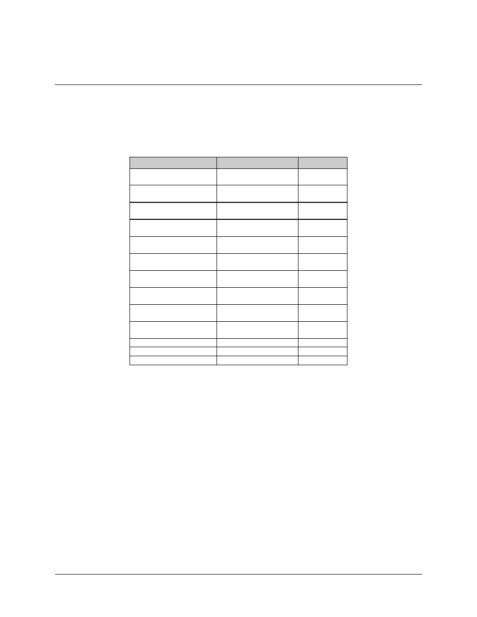
EIA-422/449 Interface Connector Pinouts
The EIA
-
422/449 interface is provided on a 37-pin female D connector accessible on the
rear panel of the modem. Screw locks are provided for mechanical security of the mating
connector.
Signal Function
Name
Pin #
Send Data
SD-A
SD-B
4
22
Send Timing
ST-A
ST-B
5
23
Receive Data
RD-A
RD-B
6
24
Request to Send
EIA-A
(See Note)
EIA-B
(See Note)
7
25
Receiver Timing
RT-A
RT-B
8
26
Clear to Send
CS-A
(See Note)
CS-B
(See Note)
9
27
Data Mode
DM-A
DM-B
11
29
Receiver Ready
RR-A
RR-B
13
31
Terminal Timing
TT-A
TT-B
17
35
Master Clock (input)
MC-A
MC-B
16
34
Demod Fault
–
21
Mod Fault
–
3
Signal Ground
SG
1, 19, 20, 37
Note: The EIA and CS lines are jumpered together on the demod/M&C card
(AS/4973-2), since the modem does not support polled operation.