Demodulator checkout, 2 demodulator checkout – Comtech EF Data SNM-1001 User Manual
Page 48
SNM-1001 Network Control Modem
Maintenance
Rev. 1
5–3
5.1.2 Demodulator
Checkout
The input to the demodulator card must be set within the proper frequency and power
level ranges for the demodulator to lock to the signal. Refer to Figure 5-2 and the table
below to check for proper E
b
/N
0
level.
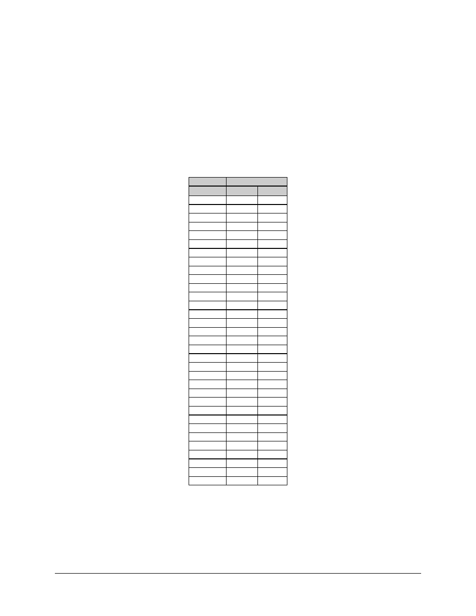
The following table lists Comtech EFData’s conversion of (S+N)/N to S/N and E
b
/N
0
for
1/2 data rate:
(dB)
Code Rate 1/2
(S+N)/N
S/N
E
b
/N
0
4.0
1.8
1.8
4.5
2.6
2.6
5.0
3.3
3.3
5.5
4.1
4.1
6.0
4.7
4.7
6.5
5.4
5.4
7.0
6.0
6.0
7.5
6.6
6.6
8.0
7.3
7.3
8.5
7.8
7.8
9.0
8.4
8.4
9.5
9.0
9.0
10.0
9.5
9.5
10.5
10.1
10.1
11.0
10.6
10.6
11.5
11.2
11.2
12.0
11.7
11.7
12.5
12.2
12.2
13.0
12.8
12.8
13.5
13.3
13.3
14.0
13.8
13.8
14.5
14.3
14.3
15.0
14.9
14.9
15.5
15.4
15.4
16.0
15.9
15.9
16.5
16.4
16.4
17.0
16.9
16.9
17.5
17.4
17.4
18.0
17.9
17.9
18.5
18.4
18.4
19.0
18.9
18.9
19.5
19.5
19.5
20.0
20.0
20.0
Figure 5-2 is an example of the typical output spectrum noise for a 1/2 rate carrier
operating at an E
b
/N
0
of 8.0 dB. (S+N)/N is measured by taking the average level of the
noise and the average level of the top of the modem spectrum as shown. Use this
measurement for the first column on the above table. Read across the page to find the
S/N and E
b
/N
0
for the specific code rate.